NoteAction
Shown in the figure Location of arm system on
page 202.
xx0600003070
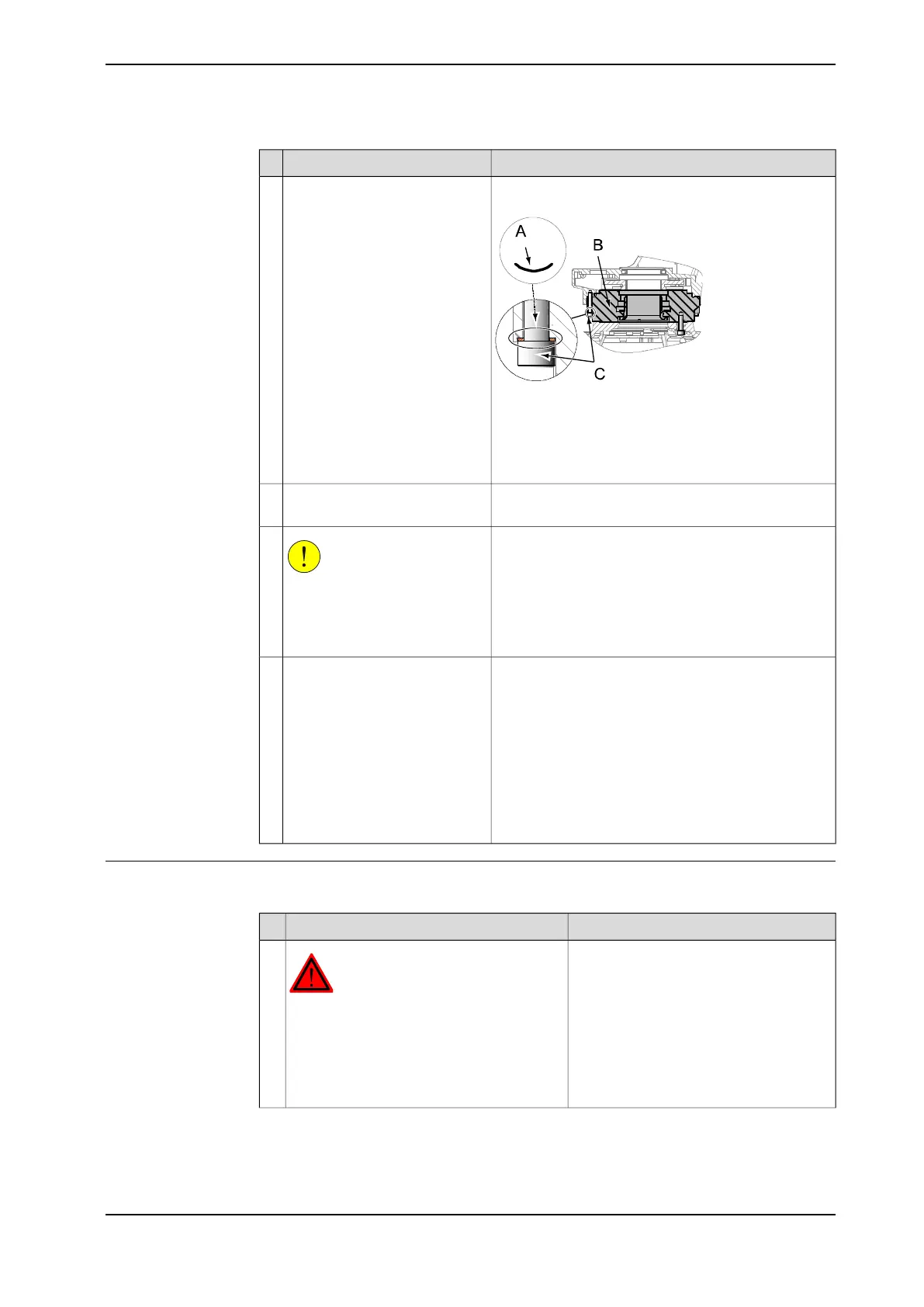
Unfasten the arm system from
the base by unscrewing its 16
attachment screws.
12
Parts:
• A: Serrated lock washer
• B: Gearbox axis 1
• C: Attachment screws M12x80
Art. no. is specified in section Required equipment on
page 202.
Fit two guide pins in two oppos-
ite screw holes.
13
CAUTION
The complete arm system
weighs 590 kg! All lifting equip-
ment used must be sized accord-
ingly!
14
Make sure all hooks and attachments stay in the cor-
rect position while lifting the arm system and that the
lifting accessory does not wear against sharp edges.
Lift the arm system carefully and
secure it in a safe area.
Always move the robot at very
low speeds, making sure it does
not tip.
Continue lifting even if the arm
system turns out to be unbal-
anced despite earlier adjust-
ments! The risk of damaging the
interfaces is bigger if the load is
lowered unbalanced!
15
Refitting, arm system
The procedure describes how to lift and refit the complete arm system.
NoteAction
DANGER
Turn off all:
• electric power supply to the robot
• hydraulic pressure supply to the robot
• air pressure supply to the robot
Before entering the robot working area.
1
Continues on next page
Product manual - IRB 6620 207
3HAC027151-001 Revision: T
© Copyright 2006-2018 ABB. All rights reserved.
4 Repair
4.3.3 Replacement of complete arm system
Continued
 Loading...


