NoteAction
Art. no. is specified in Required equip-
ment on page 277.
xx0600003126
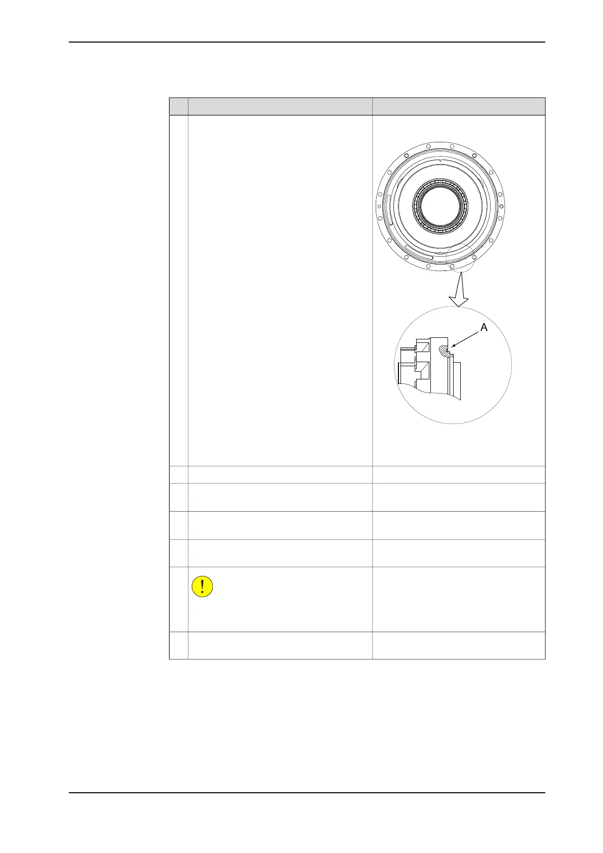
Make sure the o-ring is fitted to the gearbox
as shown in the figure to the right.
Lightly lubricate the o-ring with grease.
2
• A : O-ring (Gearbox shown from
the side)
Use some grease to attach them.Fit the three o-rings (23x3.6).3
Shown in the figure Location of gearbox
axis 1 on page 277.
Refit the protection pipe axis 1 in the center
of gearbox 1 with its attachment screws.
4
Art. no. is specified in Required equip-
ment on page 277.
Fit two lifting eyes on each side of the gear-
box and secure it with a roundsling.
5
Fit two guide pins in two of the attachment
holes, parallel to each other.
6
CAUTION
The gearbox weighs 108 kg! All lifting
equipment used must be sized accordingly!
7
Lift the gearbox on to the guide pins and
lower it carefully to its mounting position.
8
Continues on next page
Product manual - IRB 6620 281
3HAC027151-001 Revision: T
© Copyright 2006-2018 ABB. All rights reserved.
4 Repair
4.7.1 Replacement gearbox axis 1
Continued
 Loading...


