NoteAction
Shown in the figure Location of arm sys-
tem on page 207.
Remove the guide pins and secure the arm
system to the base with its 24 attachment
screws and washers.
10
M12 x 70, tightening torque: 115 Nm.
Reused screws may be used, providing
they are lubricated as detailed in section
Screw joints on page 377 before fitting.
xx0600002734
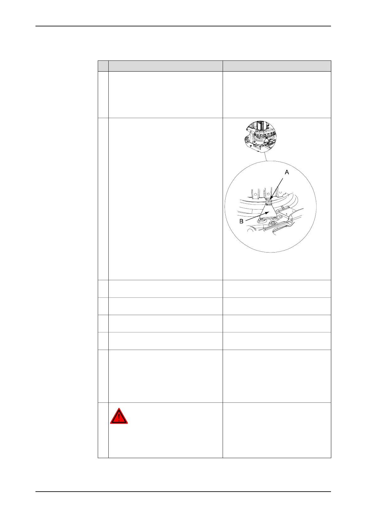
Refit the block for calibration at the bottom
of the frame.
Also refit the axis 1 calibration plate.
11
• A: Block for calibration
• B: Calibration plate axis 1
Detailed in section Replacing motor, axis
1 on page 274.
Refit the axis-1 motor.12
Detailed in section Performing a leak-
down test on page 174.
Perform a leak-down test of the axis-1
gearbox.
13
Detailed in section Replacement of cable
harness, lower end (axes 1-3) on page 181.
Refit the cabling in the base.14
Detailed in section Changing oil, axis-1
gearbox on page 146.
Refill the gearbox with lubricating oil.15
Pendulum Calibration is described in Op-
erating manual - Calibration Pendulum,
enclosed with the calibration tools.
Recalibrate the robot.16
Axis Calibration is described in Calibrating
with Axis Calibration method on page 352.
General calibration information is included
in section Calibration on page 341.
DANGER
Make sure all safety requirements are met
when performing the first test run. These are
further detailed in the section First test run
may cause injury or damage on page 28.
17
216 Product manual - IRB 6660
3HAC028197-001 Revision: S
© Copyright 2007-2018 ABB. All rights reserved.
4 Repair
4.3.5 Replacement of complete arm system
Continued