NoteAction
See the previous figure!Insert two screws, M12x50 in the holes to
neutralize the spring force. Screw in the
screws until they have proper contact with
the cylinder inside.
11
The length of the cylinder is now locked
and the balancing device is unloaded. It
should now be possible to easily rotate the
balancing device.
DANGER
Turn off all:
• electric power supply
• hydraulic pressure supply
• air pressure supply
to the robot, before entering the robot
working area.
12
Detailed in section Draining, axes 2 and 3
on page 151.
Note
Time-consuming activity!
Drain the gearbox.13
Remove the motor cables of axis-2 or axis-
3 motor, depending on which gearbox is
being removed. Protect the cables from
getting damaged and from oil spill.
14
Remove one gearbox at a time!15
Detailed in section Replacing motors, axes
2 and 3 on page 281
Remove the axis-2 or axis-3 motor, depend-
ing on which gearbox is being removed.
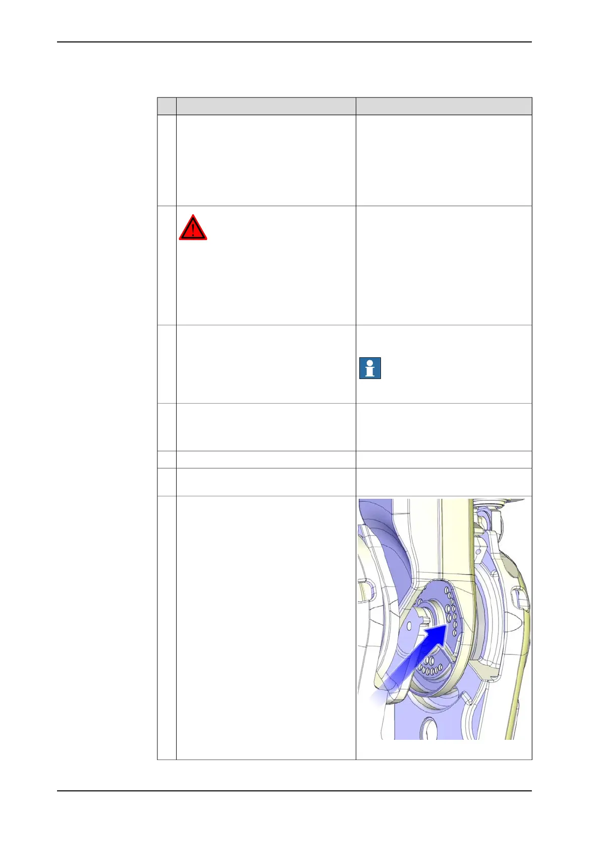
16
xx1000001405
Remove all remaining attachment screws
that secure the gearbox to the lower arm
system.
Axis 2: M16 and M12.
Axis 3: M12.
17
Continues on next page
328 Product manual - IRB 6660
3HAC028197-001 Revision: S
© Copyright 2007-2018 ABB. All rights reserved.
4 Repair
4.7.2 Replacing the gearbox, axes 2- 3
Continued