10 Reference Information
Product Manual, Control Cabinet IRC5P 3HNA009834-001 en Rev.06 209
10.1 Cable Information
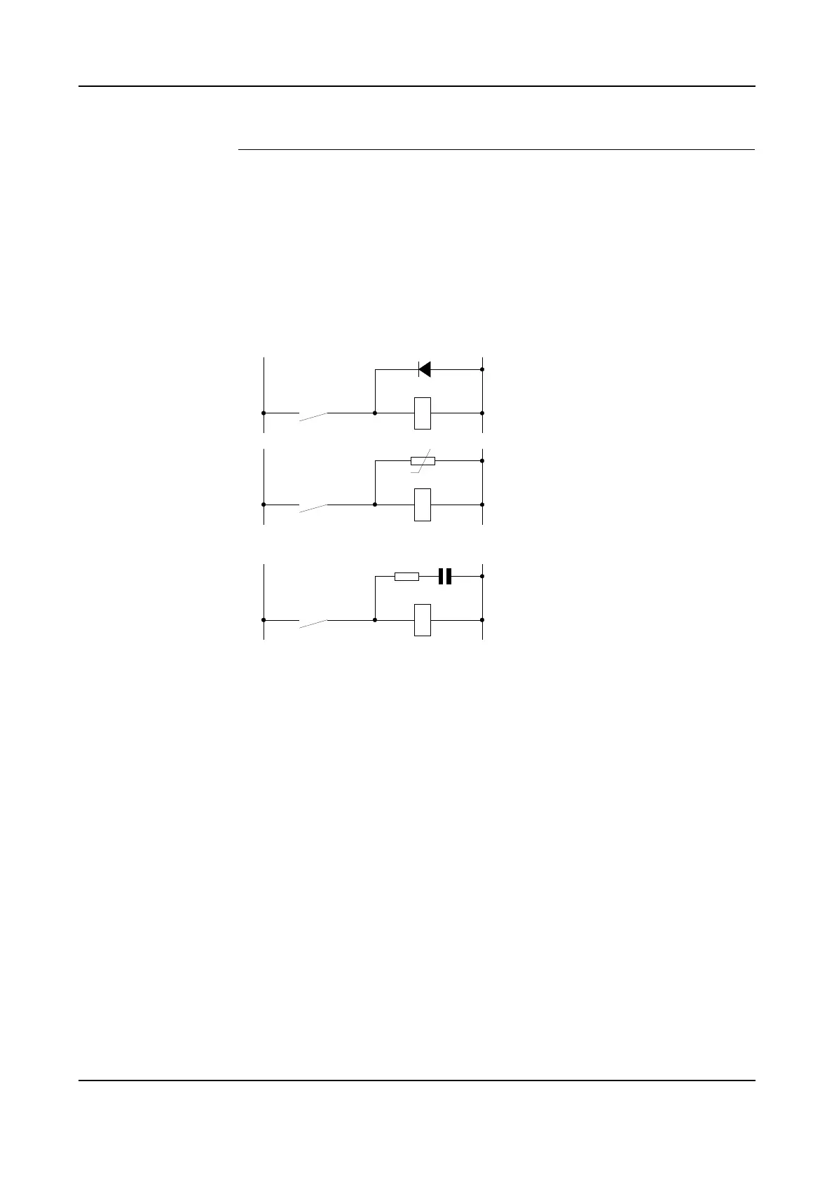
Interference Elimination Internal relay coils and other units that can generate interference inside the
controller are neutralized. External relay coils, solenoids and other units must be
clamped in a similar way. The illustration in Figure 87 shows how this can be done.
Note that the turn-off time for DC relays increases after neutralization, especially if
a diode is connected across the coil. Varistors give shorter turn-off times.
Neutralizing the coils lengthens the life of the switches that control them.
Figure 87 Examples on how peripheral equipment can be neutralized
+24 VDC 0 Volt
+24 V, DC or AC voltage 0 Volt
R
C
The diode is to be dimensioned for the
same current as the relay coil, and a
voltage of twice the supply voltage.
The varistor is to be dimensioned for
the same energy as the relay coil, and
a voltage of twice the supply voltage.
R 100 ohm, 1W
C 0.1 - 1 µF (typically 0.47 µF
> 500 V max. voltage
125 V nominal voltage