Manual Power Quality Filter PQFS Commissioning instructions 151
the current should point towards the PQF. Do not forget to remove the shorts on
the CT secondary (if present) before making the measurement.
X21.1
X21.2
X21.3
X21.4
X21.5
X21.6
X21.7
X21.8
X21.9
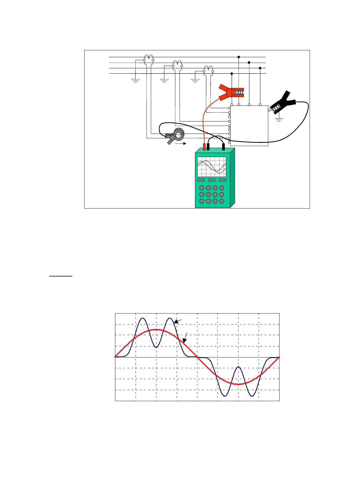
Figure 75: Connection of the scopemeter for checking the CT in phase L1
On the scopemeter screen, two waveforms should appear. The voltage waveform should
be approximately a sine wave and the current waveform would normally be a well-
distorted wave because of harmonic distortion. Usually, it is quite easy to extrapolate
the fundamental component as it is the most important one (Figure 76).
Remark: If the earthing of the system is bad, the phase to ground voltage may appear
like a much distorted waveform. In this case, it is better to measure the phase-to-phase
voltage (move the black clamp to the phase L2) and subtract 30° on the measured phase
shift.
Figure 76: Extrapolation of the fundamental component from a distorted waveform
From the fundamental component of both signals, the phase shift must then be
evaluated (Figure 77).The time ∆T between zero crossing of the rising (falling) edge of
both traces must be measured and converted to a phase shift ϕ by the following formula: