152 Commissioning instructions Manual Power Quality Filter PQFS
where T1 is the fundamental period duration.
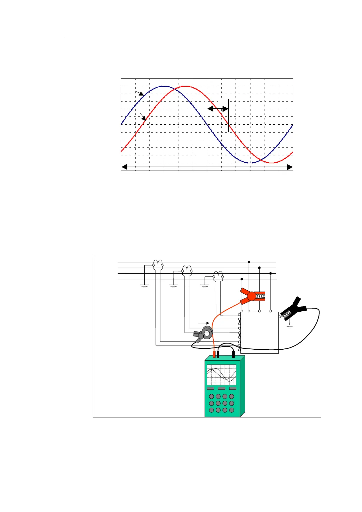
For an inductive and non-regenerative load, the current signal should lag the voltage by
a phase shift lower than 90°.
Figure 77: Phase shift evaluation between two waveforms
8.6.2.3.2 Measurement of the CT in phase L2 and L3 (Figure 78 and Figure 79)
The same operations as those described in the previous paragraph must be repeated
with the phase L2 (Figure 78) and phase L3 (Figure 79).
For a balanced load (which is usually the case in most of the three phase systems), the
phase shift should be approximately the same for all the three phases.
X21.1
X21.2
X21.3
X21.4
X21.5
X21.6
X21.7
X21.8
X21.9
Figure 78: Connection of the scopemeter for checking CT in phase L2