Manual Power Quality Filter PQFS Commissioning instructions 153
X21.1
X21.2
X21.3
X21.4
X21.5
X21.6
X21.7
X21.8
X21.9
Figure 79: Connection of the scopemeter for checking CT in phase L3
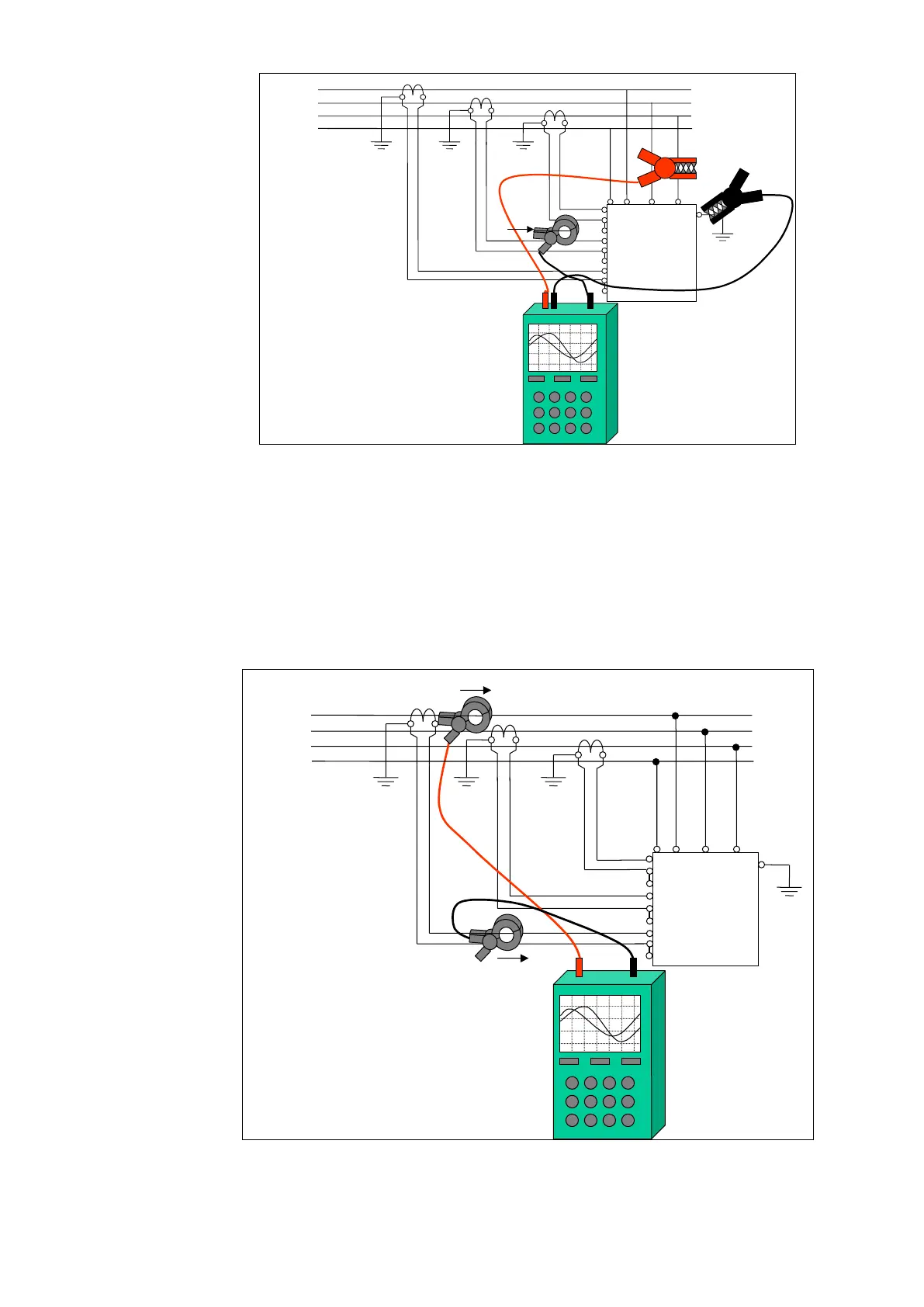
8.6.2.3.3 Checking the correct connection of the CTs with two current probes
If the main bus bar is available and all security rules are taken, it is possible to use the
two-channel scopemeter in order to see if the current measured through the CT is
matching the real current in the bus. Connect the current probes as shown on Figure 80.
The two traces must be in phase and of the same shape (the magnitude could be
different as the gains are different) if the wiring is correct.
X21.1
X21.2
X21.3
X21.4
X21.5
X21.6
X21.7
X21.8
X21.9
Figure 80: Connection of the scopemeter for checking the CT in phase L1 by
comparing the currents