20 FEP630, FEH630 ELECTROMAGNETIC FLOWMETER | OI/FEP630/FEH630-EN REV. D
… 5 Installation
… Installation conditions
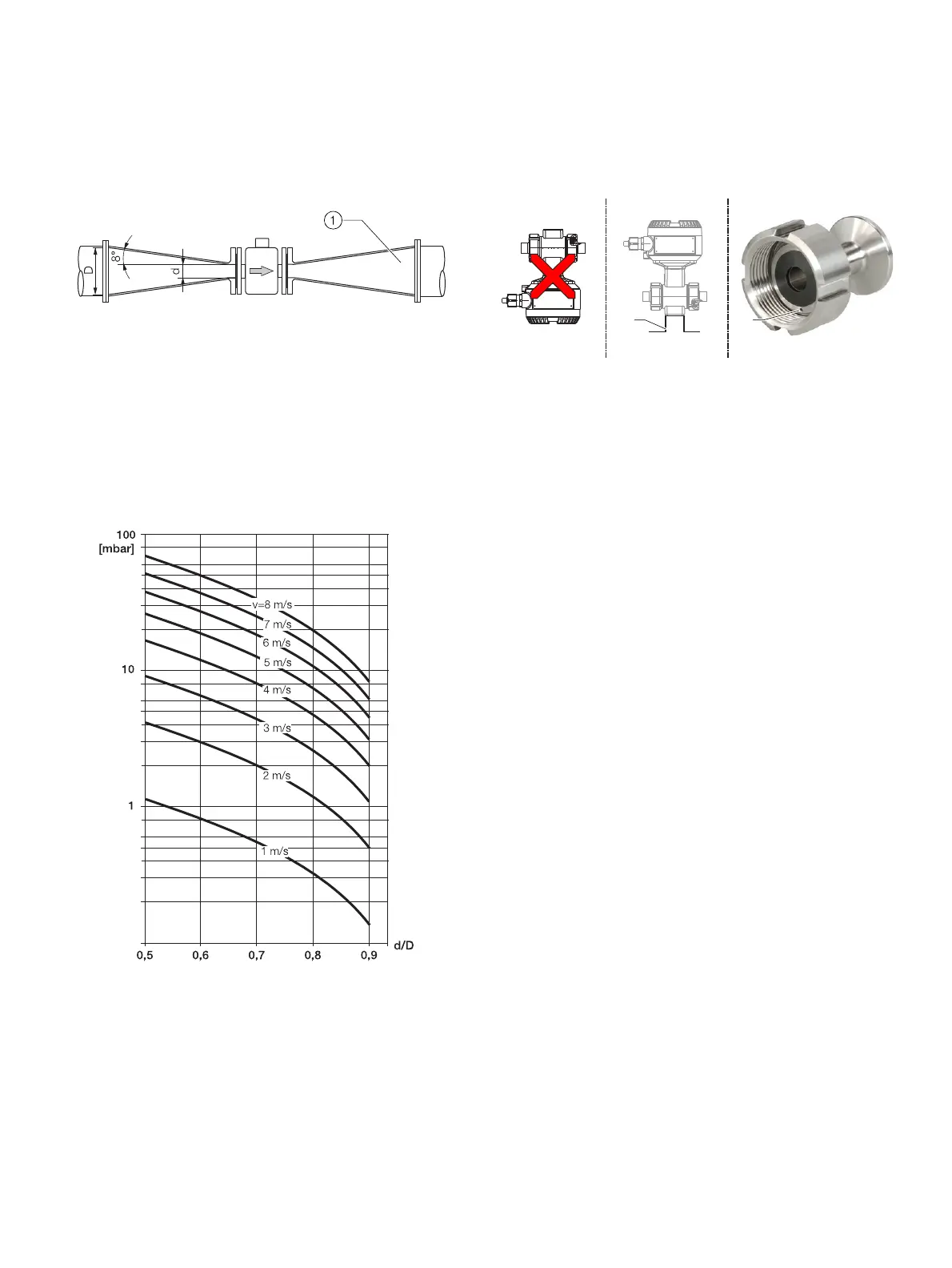
Installation in piping with larger nominal diameter
1 Reducer
Figure 20: Using reducers
Determine the resulting pressure loss when using reducers:
1. Determine diameter ratios d/D.
2. .Determine the flow velocity based on the flow rate
nomogram (Figure 21).
3. Read the pressure loss on the Y-axis in Figure 21.
Figure 21: Flow rate nomogram for flange transition piece at α/2 = 8°
Installation in 3A compliant installations
G12016
1 2
AB C
1 Angel bracket 2 Leakage hole
Figure 22: 3A compliant installation
Please observe the following points:
A Do not install the device vertically with the terminal box
or transmitter housing pointing downward.
B The ‘angel bracket’ option is not 3A compliant.
C Please make sure that the leakage hole of the process
connection is located at the lowest point of the installed
device.
• A vertical mounting position is preferred. For a horizontal
mounting position, make sure that the sensor is installed
to be self-draining.
• Make sure that the cover of terminal box and / or
transmitter housing is properly sealed. There can be no
gaps between the housing and the cover.
Only devices with the following process connections fulfill 3A
compliance.
• Welded spuds
• Tri-clamp

 Loading...


