FEP630, FEH630 ELECTROMAGNETIC FLOWMETER | OI/FEP630/FEH630-EN REV. D 37
Pin assignment
G12153
A
LN
1+ 2-
PE
B
GND
AB
+
-
+
-
+
HART
Uco
32 31
V3
V4 V1 V2
41
52
42
51
+
Oc2 Oc1
AB
UFE
GND
UFE
B
≤ 200 m
( 656 ft)≤
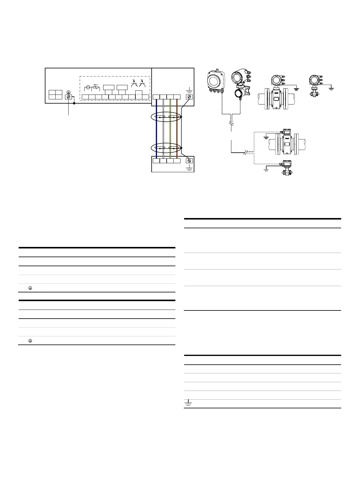
A Connections for power supply and inputs / outputs
B Connections for signal cable (remote mount design only)
Figure 45: Electrical connections
Change from one to tw o columns
Note
For additional information on the grounding of the transmitter,
see Grounding on page 18.
Connections for the power supply
AC power supply
Terminal Function / comments
L Phase
N Neutral conductor
PE / Protective earth (PE)
DC voltage supply
Terminal Function / comments
1+ +
2− −
PE / Protective earth (PE)
Connections for inputs and outputs
Terminal Function / comments
Uco / 32
31 / 32
Current output 4 to 20 mA- / HART® output, active
or
Current output 4 to 20 mA- / HART® output, passive
41 / 42 Passive digital output DO1
51 / 52 Passive digital output DO2
V1 / V2
V3 / V4
Plug-in card, slot OC1
Plug-in card, slot OC2
For details, see Optional plug-in cards on page 26.
Connecting the signal cable
Only for remote mount design.
The sensor housing and transmitter housing must be connected
to potential equalization.
Terminal Function / comments
U
FE
Sensor power supply
GND Ground
A Data line
B Data line
Functional earth / Shielding

 Loading...


