38 FEP630, FEH630 ELECTROMAGNETIC FLOWMETER | OI/FEP630/FEH630-EN REV. D
… 6 Electrical connections
… Pin assignment
Electrical data for inputs and outputs
Note
• An additional document with Ex safety instructions is
available for measuring systems that are used in potentially
explosive atmospheres.
• Ex safety instructions are an integral part of this manual. As
a result, it is crucial that the installation guidelines and
connection values it lists are also observed.
The icon on the name plate indicates
the following:
Power supply
AC power supply
Terminals L / N
Operating voltage 100 to 240 V AC (−15 % / +10 %), 47 to 64 Hz
Power consumption S
max
: < 20 VA
Power-up current 18.4 A, t < 3 ms
DC voltage supply
Terminals 1+ / 2−
Operating voltage 16.8 to 30 V DC
Ripple < 5 %
Power consumption P
max
: < 20 W
Power-up current 21 A, t < 10 ms
Current output Uco / 32, 31 / 32
Can be configured for outputting mass flow and volume flow via
the on-site software.
G11596-02
+
-
AB
IE
32-
Uco
32-
IE
31+
R
B
R
B
Uq
31+
Uco
+
-
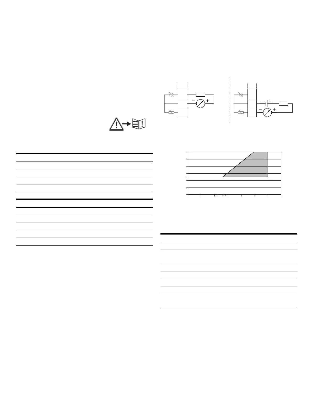
A Current output Uco / 32, active B Current output 31 / 32, passive
Figure 46: (I = internal, E = external, R
B
= load)
G10323-02
0
0
100
200
300
400
500
600
5101520253035
RB [Ω]
Uq [V]
Permissible source voltage U
q
for passive outputs in relation to load
resistance R
B
where I
max
= 22 mA. = Permissible range
Figure 47: Source voltage for passive outputs
Current output Active Passive
Terminals Uco / 32 31 / 32
Output signal 4 to 20 mA or
4 to 12 to 20 mA switchable
4 to 20 m
Load R
B
250 Ω ≤ R
B
≤ 300 Ω 250 Ω ≤ R
B
≤ 600 Ω
Source voltage U
q
* — 13 V ≤ U
q
≤ 30
Measuring error < 0.1 % of measured value
Resolution 0.4 µA per digit
Insulation The current output and digital outputs are electrically
isolated.
* Source voltage U
q
depends on the load R
B
and must be within the
permissible range.
For information on communication via the HART protocol, refer
to HART® communication on page 49.

 Loading...


