28 FEP630, FEH630 ELECTROMAGNETIC FLOWMETER | OI/FEP630/FEH630-EN REV. D
… 5 Installation
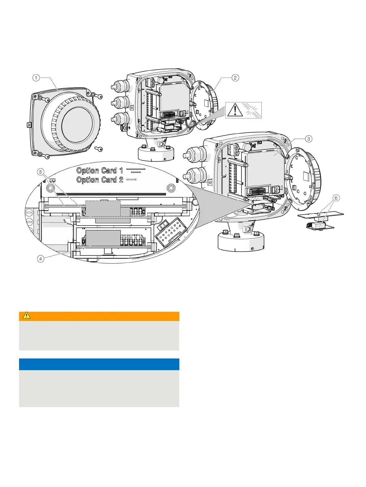
… Installing the plug-in cards
1 Cover
2 LCD indicator
3 Slot OC1
4 Slot OC2
5 Plug-in cards
Figure 33: Installation of plug-in cards (example, single-compartment housing)
Change from one to tw o columns
WARNING
Risk of injury due to live parts!
When the housing is open, contact protection is not provided
and EMC protection is limited.
• Before opening the housing, switch off the power supply.
NOTICE
Damage to components!
The electronic components of the printed circuit board can be
damaged by static electricity (observe ESD guidelines).
• Make sure that the static electricity in your body is
discharged before touching electronic components.
1. Switch off the power supply.
2. Unscrew / remove the cover.
3. Remove the LCD indicator. Ensure that the cable harness is
not damaged.
Insert the LCD indicator into the bracket
(only for single-compartment housings)
4. Remove frontend board (only in integral mount design and
dual-compartment housing). Ensure that the cable harness is
not damaged.
5. Insert the plug-in card in the corresponding slot and engage.
Ensure that the contacts are aligned correctly.
6. Attach the frontend board, insert the LCD indicator and
screw on / replace the cover.
7. Connect outputs V1 / V2 and V3 / V4 in accordance with
Electrical connections on page 29.
8. After powering up the power supply, configure the plug-in
card functions.

 Loading...


