ABB Network Partner AB
Apparatus control
Version 1.0-00
1MRK 580 150-XEN
Page 6 - 36
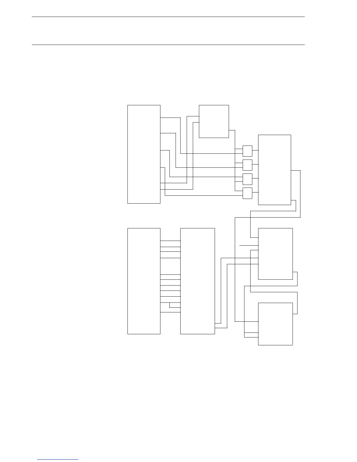
4.2.3 Station MMI The connection to the station MMI is made via EVENT-block and MultC-
mdFunc-block in a standardized way. Fig. 21 shows the command con-
nections between the command blocks and the apparatus control modules.
Fig. 21 also shows how the BLKCON modules are used.
Fig. 21 Command connections between the station MMI and
apparatus control modules
Fig. 22 shows the signals from the apparatus control modules for one
apparatus that will be sent to the station MMI. The event input 7 can be
connected to the tripping logic to indicate on the station MMI that the cir-
cuit breaker was opened due to a trip from the protection. The inputs 3 and
MultCmdFunc
OUT1
OUT2
OUT3
OUT4
OUT5
OUT6
BAYCON
S_R
S_S
&
STATION
&
&
&
BLK_OP
DBLK_OP
BLK_UPD
DBLK_UPD
BLKCMD1
DBLCMD1
BLKCMD2
DBLCMD2
BLK_OUT1
BLK_OUT2
BLKCONK
SWICON
Apparatus1
BLKCONL
Apparatus1
BLK_1_1
BLK_1_2
BLK_1_3
BLK_OUT1
MA_UPD_P
UPD_BLK
BLK_OPEN
BLK_CLOS
I/O error
MultCmdFunc COMCON
S_BLK_OP
S_DBL_OP
S_BL_UPD
S_PR_UPD
S_MA_U_O
S_MA_U_C
S_CANCEL
S_SEL_O
S_SEL_C
S_OPEN
S_CLOSE
S_IR_OVR
Apparatus1
Apparatus commands
Bay commands
from station
MMI
from station MMI
BLKCMD1
DBLCMD1
BLK_OP
DBL_OP
OUT7
OUT8
OUT9
OUT10
Defined as pulse outputs
Defined as pulse outputs
OUT11
OUT12
OUT13
OUT14
OUT15
OUT16
OUT1
OUT2
OUT3
OUT4
OUT5
OUT6
OUT7
OUT8
OUT9
OUT10
OUT11
OUT12
OUT13
OUT14
OUT15
OUT16
(X80150-21