L1
(A)
L2
(B)
L3
(C)
Protected Object
CT 1500/5
Star/Wye
Connected
7
8
9
10
11
12
1
2
3
4
5
6
AI01 (I)
AI02 (I)
AI03 (I)
AI04 (I)
AI05 (I)
AI06 (I)
6
IED
X1
R1
1
2
4 5
V
R2
1
3
4
2
1 2 3
N
1-Ph Plate with Metrosil and Resistor
2
3
5
4
N
L1
(A)
L2
(B)
L3
(C)
CT 1500/5
1
ANSI09000170-5-en.vsdx
SMAI2
BLOCK
REVROT
^GRP2_A
^GRP2_B
^GRP2_C
^GRP2_N
G2AI3P
G2AI1
G2AI2
G2AI3
G2AI4
G2N
ANSI09000170 V5 EN-US
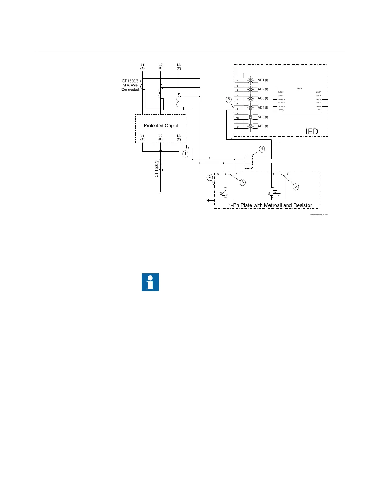
Figure 51: CT connections for restricted earth fault protection
Pos Description
1 Scheme grounding point
Ensure that only one grounding point exists in this scheme.
2 One-phase plate with stabilizing resistor and metrosil. Protective ground is a separate 4 mm screw
terminal on the plate.
3 Necessary connection for the metrosil.
4 Position of optional test switch for secondary injection into the high impedance differential IED.
5 Necessary connection for stabilizing resistor.
6 How to connect the high impedance restricted earth fault protection scheme to one CT input in IED.
7.1.4 Setting guidelines
IP14945-1 v1
M13076-3 v2
The setting calculations are individual for each application. Refer to the dif
ferent
application descriptions below
.
1MRK 511 401-UUS A Section 7
Differential protection
Bay control REC670 2.2 ANSI 137
Application manual

 Loading...


