en04000487_ansi.vsd
Section 1 Section 2
A1A2_DC(BS)
B1B2_DC(BS)
AB_TRAFO ABC_BCAB_TRAFO ABC_BC
(WA1)A1
(WA2)B1
(WA7)C C
B2
A2
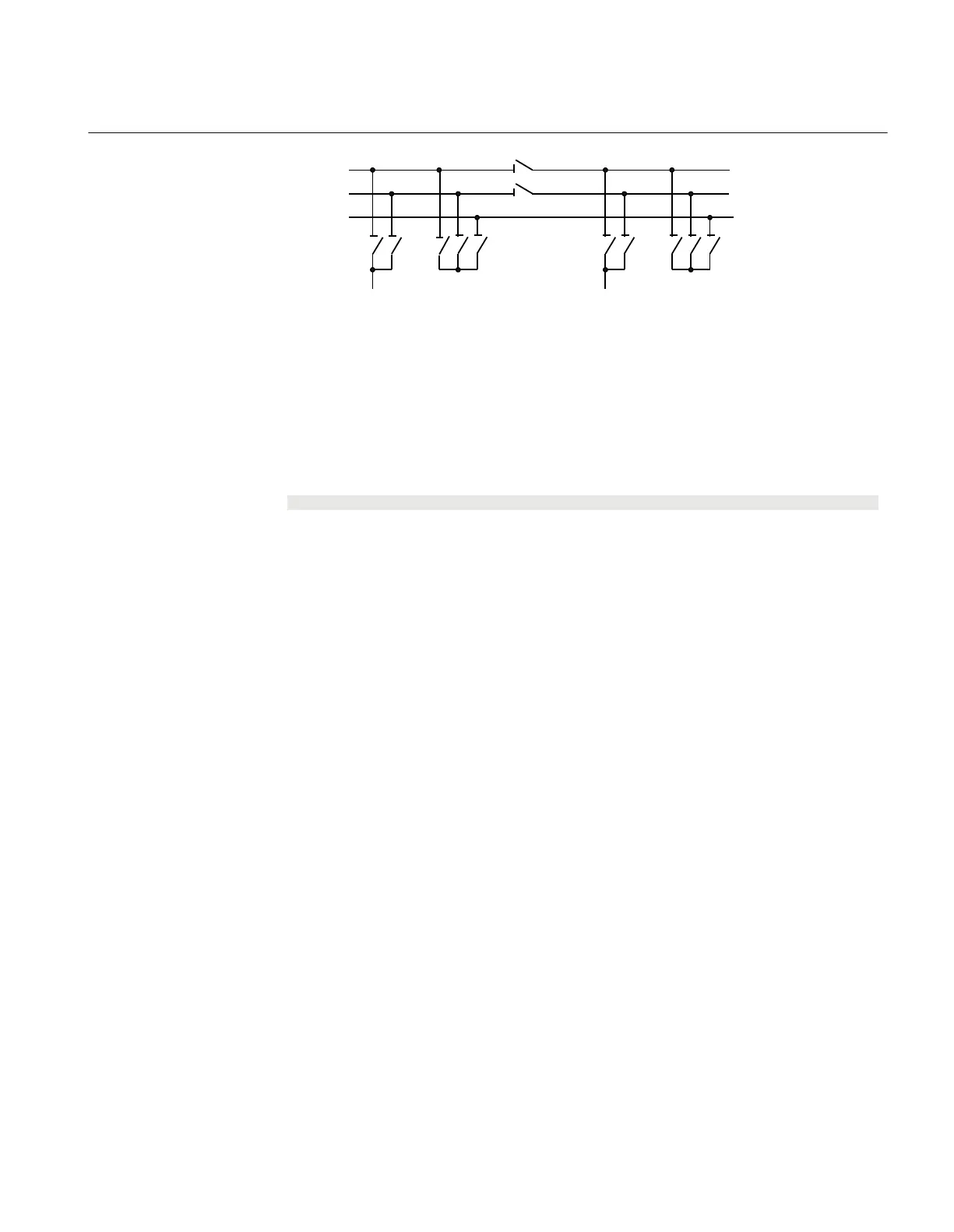
ANSI04000487 V1 EN-US
Figure 141: Busbars divided by bus-section disconnectors (circuit breakers)
The project-specific logic for input signals concerning bus-coupler are the same as the
specific logic for the line bay (ABC_LINE):
Signal
BC_12_CL A bus-coupler connection exists between busbar WA1 and WA2.
VP_BC_12 The switch status of BC_12 is valid.
EXDU_BC No transmission error from bus-coupler bay (BC).
The logic is identical to the double busbar configuration “Signals from bus-coupler“.
14.4.4.3
Configuration setting
M13566-22 v5
If there are no second busbar B and therefore no
289 disconnector, then the
interlocking for 289 is not used. The state for 289, 2189G, BC_12 are set to open by
setting the appropriate module inputs as follows. In the functional block diagram, 0 and
1 are designated 0=FALSE and 1=TRUE:
• 289_OP = 1
• 289QB2_CL = 0
• 2189G_OP = 1
• 2189G_CL = 0
• BC_12_CL = 0
• VP_BC_12 = 1
1MRK 511 401-UUS A Section 14
Control
Bay control REC670 2.2 ANSI 385
Application manual

 Loading...


