en04000503_ansi.vsd
Section 1 Section 2
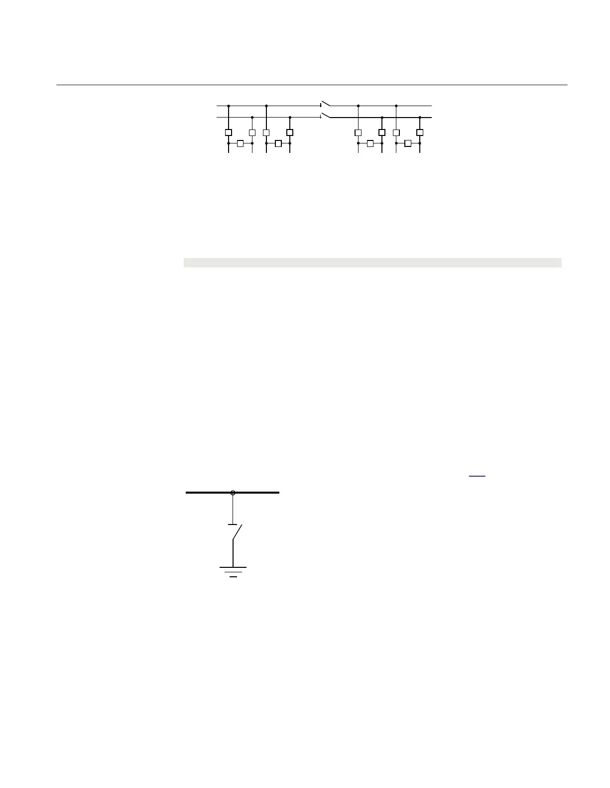
A1A2_DC(BS)
B1B2_DC(BS)
BH_LINE
(WA1)A1
(WA2)B1 B2
A2
BH_LINE
BH_LINE BH_LINE
ANSI04000503 V1 EN-US
Figure 157: Busbars divided by bus-section disconnectors (circuit breakers)
The project-specific logic is the same as for the logic for the double-breaker
configuration.
Signal
S1DC_OP All disconnectors on bus-section 1 are open.
S2DC_OP All disconnectors on bus-section 2 are open.
VPS1_DC The switch status of disconnectors on bus-section 1 is valid.
VPS2_DC The switch status of disconnectors on bus-section 2 is valid.
EXDU_BB No transmission error from breaker and a half (BH) that contains the above
information.
14.4.7 Interlocking for busbar grounding switch BB_ES (3)
IP14164-1 v4
14.4.7.1 Application
M15015-3 v7
The interlocking for busbar grounding switch (BB_ES, 3) function is used for one
busbar grounding switch on any busbar parts according to figure 158.
ANSI04000504 V1 EN-US
Figure 158: Switchyard layout BB_ES (3)
M15053-4 v4
The signals from other bays connected to the module BB_ES are described below.
1MRK 511 401-UUS A Section 14
Control
Bay control REC670 2.2 ANSI 397
Application manual

 Loading...


