ANSI09000024-1-en.vsd
~ ~
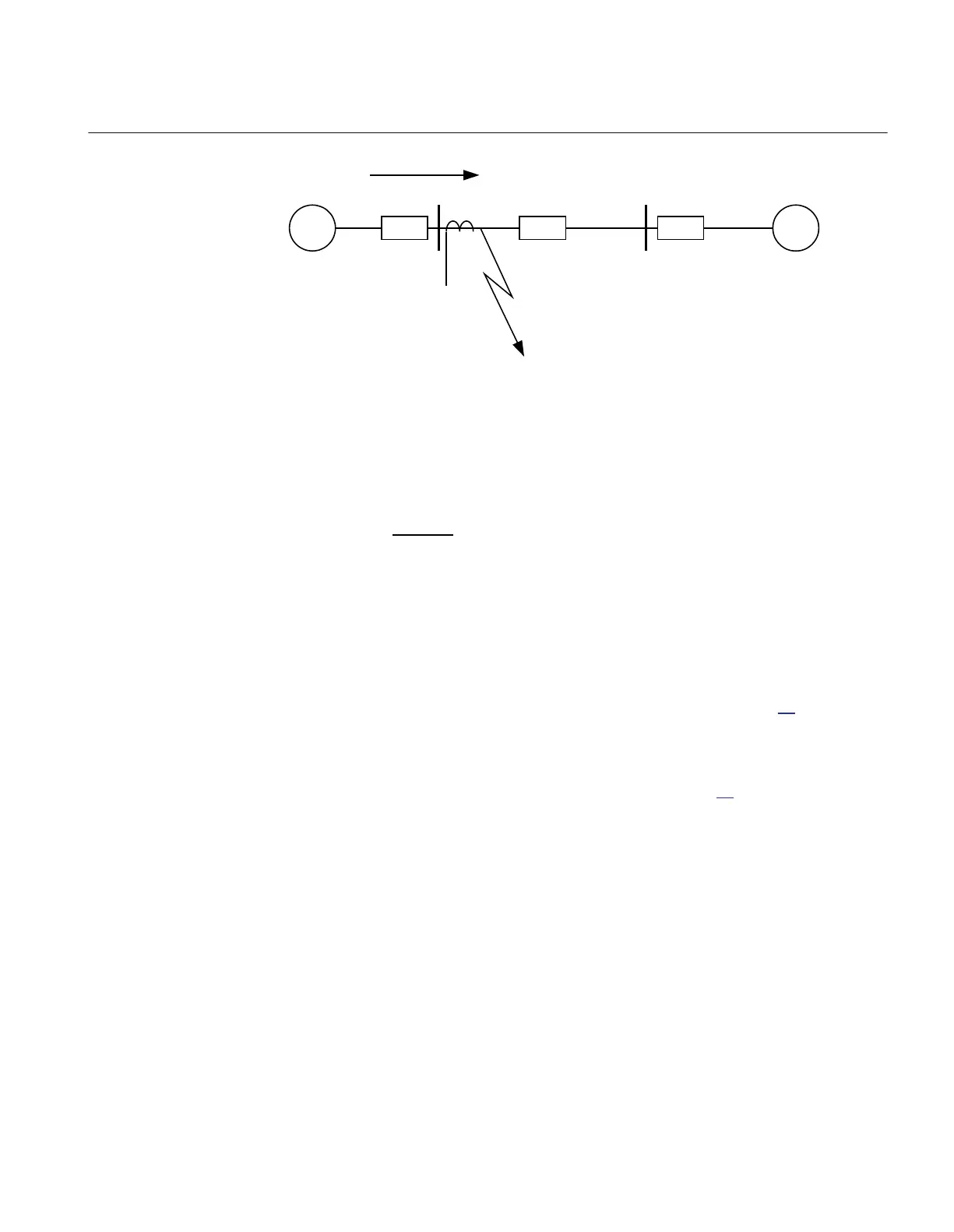
Z
A
Z
B
Z
L
A B
I
F
Fault
IED
ANSI09000024 V1 EN-US
Figure 57: Fault current: I
F
The IED setting value Pickup is given in percentage of the primary base current value,
IBase. The value for Pickup is given from this formula:
ANSIEQUATION1147 V1 EN-US (Equation 23)
8.1.3.2 Meshed network with parallel line
M12915-34 v7
In case of parallel lines, the influence of the induced current from the parallel line to
the protected line has to be considered. One example is given in Figure
58, where the
two lines are connected to the same busbars. In this case the influence of the induced
fault current from the faulty line (line 1) to the healthy line (line 2) is considered
together with the two through fault currents I
fA
and I
fB
mentioned previously. The
maximal influence from the parallel line for the IED in Figure
58 will be with a fault at
the C point with the C breaker open.
A fault in C has to be applied, and then the maximum current seen from the IED (I
M
)
on the healthy line (this applies for single-phase-to-ground and two-phase-to-
ground
faults) is calculated.
1MRK 511 401-UUS A Section 8
Current protection
Bay control REC670 2.2 ANSI 151
Application manual

 Loading...


