~ ~
Z
A
Z
B
Z
L1
A B
I
M
Fault
IED
Z
L2
M
C
Line 1
Line 2
ANSI09000025_2_en.vsd
ANSI09000025 V2 EN-US
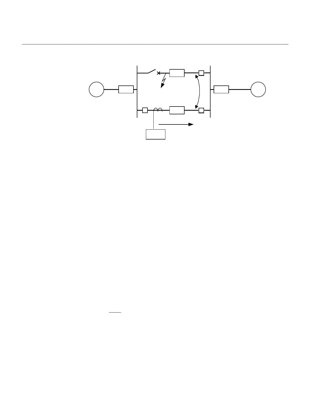
Figure 58: Two parallel lines. Influence from parallel line to the through fault
current: I
M
The minimum theoretical current setting for the overcurrent protection function (Imin)
will be:
EQUATION82 V1 EN-US (Equation 24)
Where I
fA
and I
fB
have been described in the previous paragraph. Considering the
safety margins mentioned previously
, the minimum setting (Is) for the instantaneous
phase overcurrent protection 3-phase output is then:
EQUATION83 V2 EN-US (Equation 25)
The protection function can be used for the specific application only if this setting
value is equal or less than the maximum phase fault current that the IED has to clear.
The IED setting value Pickup is given in percentage of the primary base current value,
IBase
. The value for Pickup is given from this formula:
ANSIEQUATION1147 V1 EN-US (Equation 26)
Section 8 1MRK 511 401-UUS A
Current protection
152 Bay control REC670 2.2 ANSI
Application manual

 Loading...


