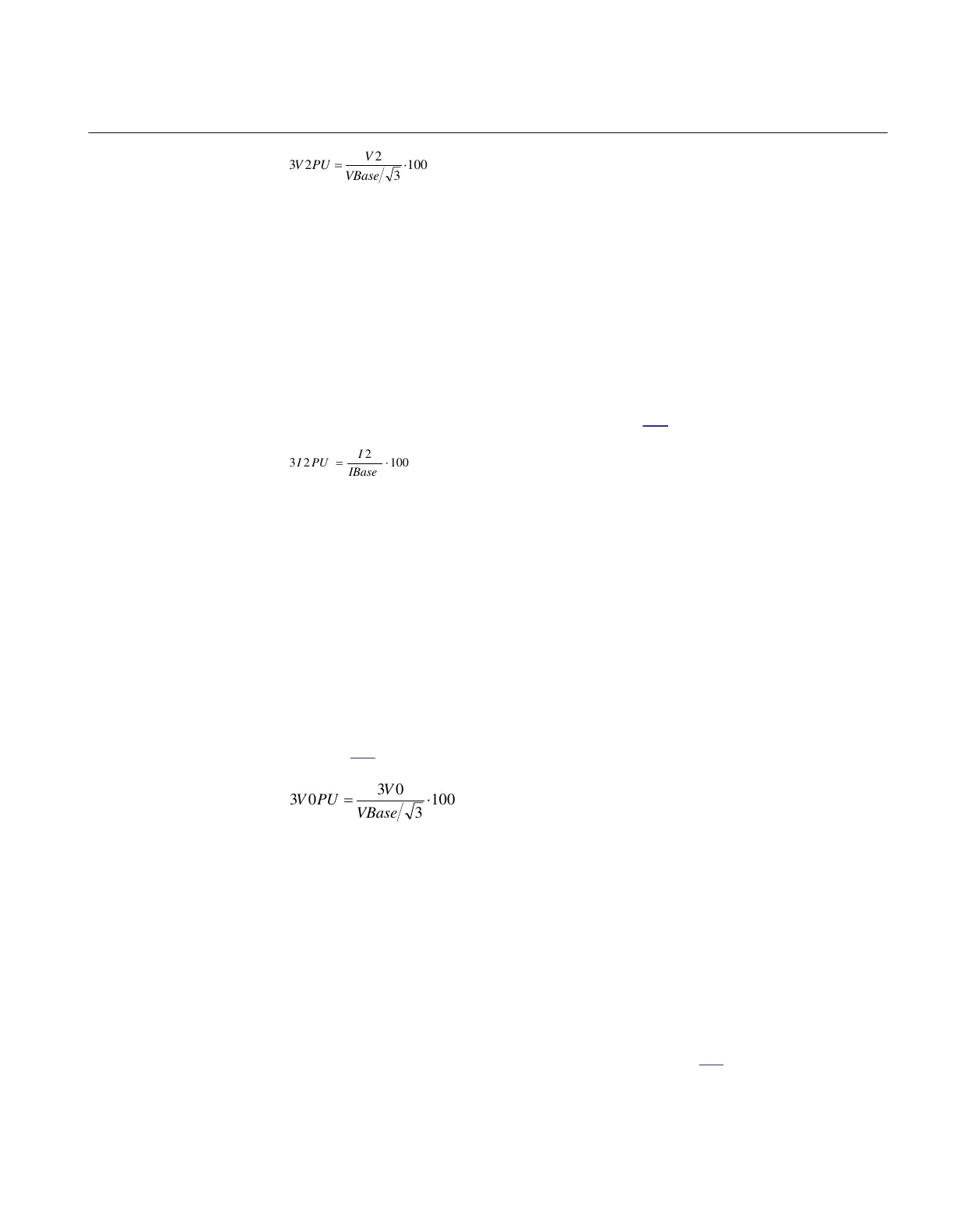
EQUATION1757-ANSI V4 EN-US (Equation 108)
where:
V2PU is the maximal negative sequence voltage during normal operation conditions, plus a margin of
10...20%
VBase
is the base voltage for the function according to the setting
GlobalBaseSel
The setting of the current limit 3I2PU is in percentage of parameter IBase. The setting
of 3I2PU must be higher than the normal unbalance current that might exist in the
system and can be calculated according to equation
109.
EQUATION1758-ANSI V4 EN-US (Equation 109)
where:
I2 is the maximal negative sequence current during normal operating conditions, plus a margin of
10...20%
IBase
is the base current for the function according to the setting
GlobalBaseSel
13.2.3.4 Zero sequence based
M13683-43 v8
The IED setting value 3V0PU is given in percentage of the base voltage VBase. The
setting of 3V0PU should not be set lower than the value that is calculated according to
equation
110.
EQUATION1759-ANSI V4 EN-US (Equation 110)
where:
3V0 is the maximal zero sequence voltage during normal operation conditions, plus a margin of
10...20%
VBase is the base voltage for the function according to the setting
GlobalBaseSel
The setting of the current limit 3I0PU is done in percentage of IBase. The setting of
pickup must be higher than the normal unbalance current that might exist in the
system. The setting can be calculated according to equation
111.
1MRK 511 401-UUS A Section 13
Secondary system supervision
Bay control REC670 2.2 ANSI 297
Application manual

 Loading...


