Signal
Q1289OPTR 189 or 289 or both are open.
VP1289TR The switch status of 189 and 289 are valid.
EXDU_12 No transmission error from the bay that contains the above information.
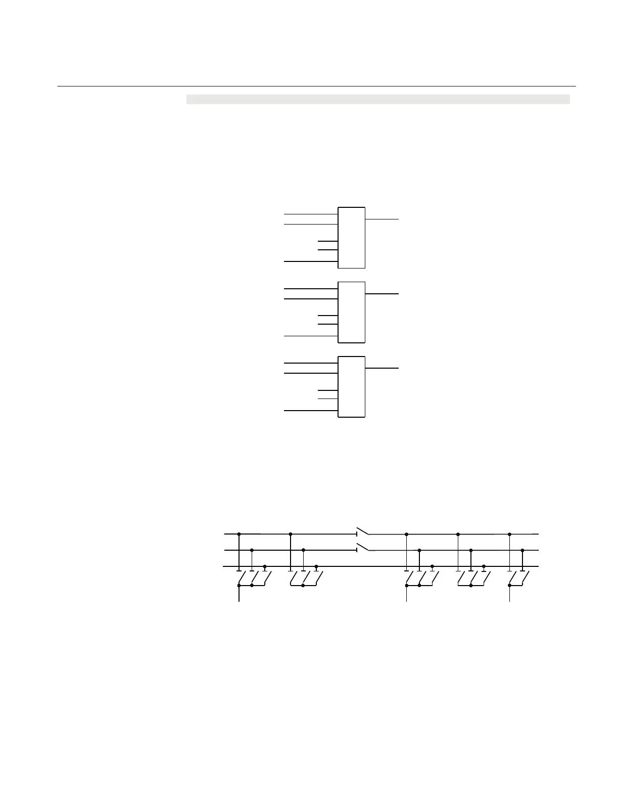
For bus-coupler bay n, these conditions are valid:
1289OPTR (bay 1)
1289OPTR (bay 2)
. . .
. . .
1289OPTR (bay n-1)
AND
BBTR_OP
VP1289TR (bay 1)
VP1289TR (bay 2)
. . .
. . .
VP1289TR (bay n-1)
AND
VP_BBTR
EXDU_12 (bay 1)
EXDU_12 (bay 2)
. . .
. . .
EXDU_12 (bay n-1)
AND
EXDU_12
en04000481_ansi.vsd
ANSI04000481 V1 EN-US
Figure 135: Signals from any bays in bus-coupler bay n
If the busbar is divided by bus-section disconnectors into bus-sections, the signals
BBTR are connected in parallel - if both bus-section disconnectors are closed. So for
the basic project-specific logic for BBTR above, add this logic:
Section 1 Section 2
A1A2_DC(BS)
B1B2_DC(BS)
ABC_LINE
ABC_BC
ABC_LINE ABC_BC
(WA1)A1
(WA2)B1
(WA7)C C
B2
A2
en04000482_ansi.vsd
AB_TRAFO
ANSI04000482 V1 EN-US
Figure 136: Busbars divided by bus-section disconnectors (circuit breakers)
1MRK 511 401-UUS A Section 14
Control
Bay control REC670 2.2 ANSI 379
Application manual

 Loading...


