en04000489_ansi.vsd
Section 1 Section 2
A1A2_BS
B1B2_BS
ABC_LINE
ABC_BC
ABC_LINE
ABC_BC
(WA1)A1
(WA2)B1
(WA7)C C
B2
A2
AB_TRAFOAB_TRAFO
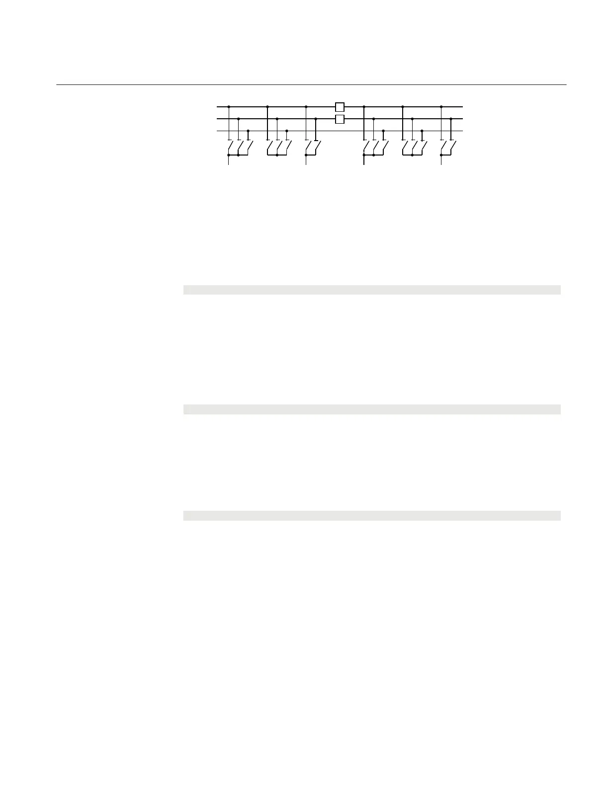
ANSI04000489 V1 EN-US
Figure 143: Busbars divided by bus-section circuit breakers
To derive the signals:
Signal
BBTR_OP No busbar transfer is in progress concerning this bus-section.
VP_BBTR The switch status of BBTR is valid.
EXDU_12 No transmission error from any bay connected to busbar 1(A) and 2(B).
These signals from each line bay (ABC_LINE), each transformer bay (AB_TRAFO),
and bus-coupler bay (ABC_BC) are needed:
Signal
1289OPTR 189 or 289 or both are open.
VP1289TR The switch status of 189 and 289 are valid.
EXDU_12 No transmission error from the bay that contains the above information.
These signals from each bus-coupler bay (ABC_BC) are needed:
Signal
BC12OPTR No bus-coupler connection through the own bus-coupler between busbar WA1 and
WA2.
VPBC12TR The switch status of BC_12 is valid.
EXDU_BC No transmission error from the bay that contains the above information.
These signals from the bus-section circuit breaker bay (A1A2_BS, B1B2_BS) are
needed.
1MRK 511 401-UUS A Section 14
Control
Bay control REC670 2.2 ANSI 387
Application manual

 Loading...


