The same type of module (A1A2_DC) is used for different busbars, that is, for both
bus-section disconnector A1A2_DC and B1B2_DC. But for B1B2_DC, corresponding
signals from busbar B are used.
en04000498_ansi.vsd
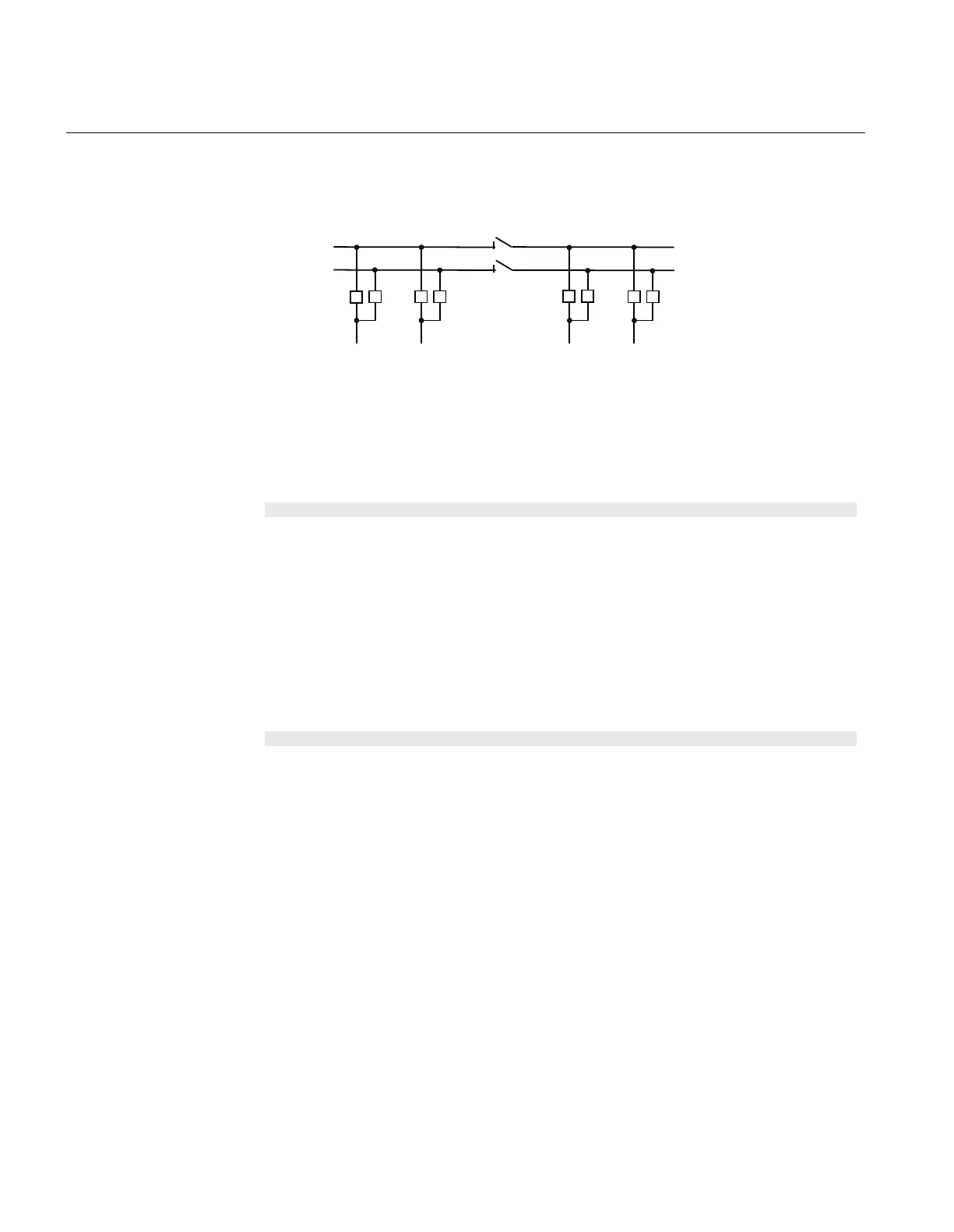
Section 1 Section 2
A1A2_DC(BS)
B1B2_DC(BS)
DB_BUS DB_BUSDB_BUS DB_BUS
(WA1)A1
(WA2)B1
B2
A2
ANSI04000498 V1 EN-US
Figure 152: Busbars divided by bus-section disconnectors (circuit breakers)
To derive the signals:
Signal
S1DC_OP All disconnectors on bus-section 1 are open.
S2DC_OP All disconnectors on bus-section 2 are open.
VPS1_DC The switch status of all disconnectors on bus-section 1 is valid.
VPS2_DC The switch status of all disconnectors on bus-section 2 is valid.
EXDU_BB No transmission error from double-breaker bay (DB) that contains the above
information.
These signals from each double-breaker bay (DB_BUS) are needed:
Signal
189OPTR 189 is open.
289OPTR 289 is open.
VP189TR The switch status of 189 is valid.
VP289TR The switch status of 289 is valid.
EXDU_DB No transmission error from the bay that contains the above information.
The logic is identical to the double busbar configuration “Signals in single breaker
arrangement”.
For a bus-section disconnector
, these conditions from the A1 busbar section are valid:
Section 14 1MRK 511 401-UUS A
Control
394 Bay control REC670 2.2 ANSI
Application manual

 Loading...


