Rline and Xline: For line voltage drop compensation, these settings give the line
resistance and reactance from the station busbar to the load point. The settings for
Rline and Xline are given in primary system ohms. If more than one line is connected
to the LV busbar
, equivalent Rline and Xline values should be calculated and given as
settings.
When the line voltage drop compensation function is used for parallel control with the
reverse reactance method, then the compensated voltage which is designated “load
point voltage” V
L
is effectively an increase in voltage up into the transformer. To
achieve this voltage increase, Xline must be negative. The sensitivity of the parallel
voltage regulation is given by the magnitude of Rline and Xline settings, with Rline
being important in order to get a correct control of the busbar voltage. This can be
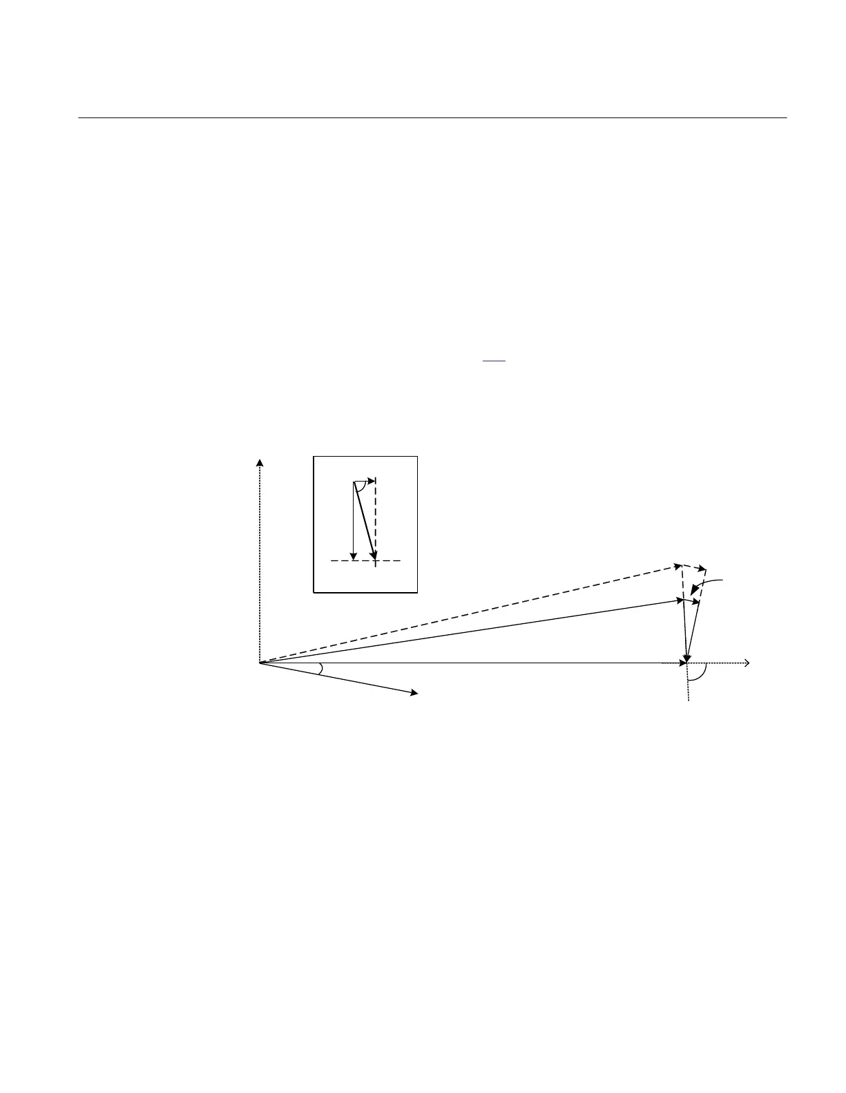
realized in the following way. Figure
172 shows the vector diagram for a transformer
controlled in a parallel group with the reverse reactance method and with no circulation
(for example, assume two equal transformers on the same tap position). The load
current lags the busbar voltage V
B
with the power factor j
and the argument of the
impedance Rline and Xline is designated j1.
V
B
jI
T
*Xline
V
L
Xline
Rline
Zline
I
T
I
T
*Rline
j
j
1
j
2
DV
en06000626_ansi.vsd
ANSI06000626 V1 EN-US
Figure 181: Transformer with reverse reactance regulation and no circulating
current
The voltage DV=V
B
-V
L
=I
T
*Rline+j I
T
*Xline has the argument j2 and it is realised that
if j2 is slightly less than -90°, then V
L
will have approximately the same length as V
B
regardless of the magnitude of the transformer load current I
T
(indicated with the
dashed line). The automatic tap change control regulates the voltage towards a set
target value, representing a voltage magnitude, without considering the phase angle.
Thus, V
B
as well as V
L
and also the dashed line could all be said to be on the target
value.
1MRK 511 401-UUS A Section 14
Control
Bay control REC670 2.2 ANSI 447
Application manual

 Loading...


