Setting Short Description Selected
value
Comments
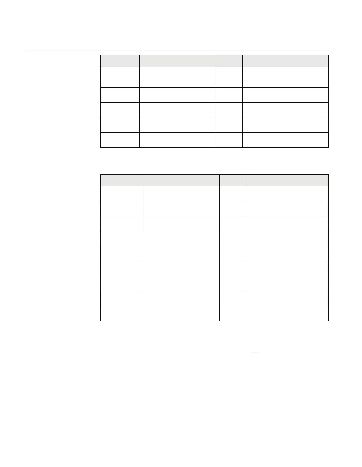
PHiHiLim
High High limit (physical value),
% of SBase
60 High alarm limit that is, extreme
overload alarm, hence it will be 415
MW.
PHiLim
High limit (physical value), in %
of SBase
50 High warning limit that is, overload
warning, hence it will be 371 MW.
PLowLim
Low limit (physical value), in % of
SBase
-50 Low warning limit -500 MW
PLowLowlLim
Low Low limit (physical value), in
% of SBase
-60 Low alarm limit -600 MW
PLimHyst
Hysteresis value in % of range
(common for all limits)
1 Set ±Δ Hysteresis 20 MW that is, 1%
of range (2000 MW)
Table 48: Settings for calibration parameters
Setting Short Description Selected
value
Comments
IMagComp5
Magnitude factor to calibrate
current at 5% of In
0.00
IMagComp30
Magnitude factor to calibrate
current at 30% of In
0.00
IMagComp100
Magnitude factor to calibrate
current at 100% of In
0.00
VAmpComp5 Magnitude factor to calibrate
voltage at 5% of Vn
0.00
VMagComp30
Magnitude factor to calibrate
voltage at 30% of Vn
0.00
VMagComp100
Magnitude factor to calibrate
voltage at 100% of Vn
0.00
IAngComp5
Angle calibration for current at
5% of In
0.00
IAngComp30
Angle pre-calibration for current
at 30% of In
0.00
IAngComp100
Angle pre-calibration for current
at 100% of In
0.00
Measurement function application for a power transformer
SEMOD54481-61 v9
Single line diagram for this application is given in figure 208.
Section 17 1MRK 511 401-UUS A
Monitoring
518 Bay control REC670 2.2 ANSI
Application manual

 Loading...


