TB82PH ATEX Product Instruction Manual ABB
10 TB82PH-ATEX-EN-A
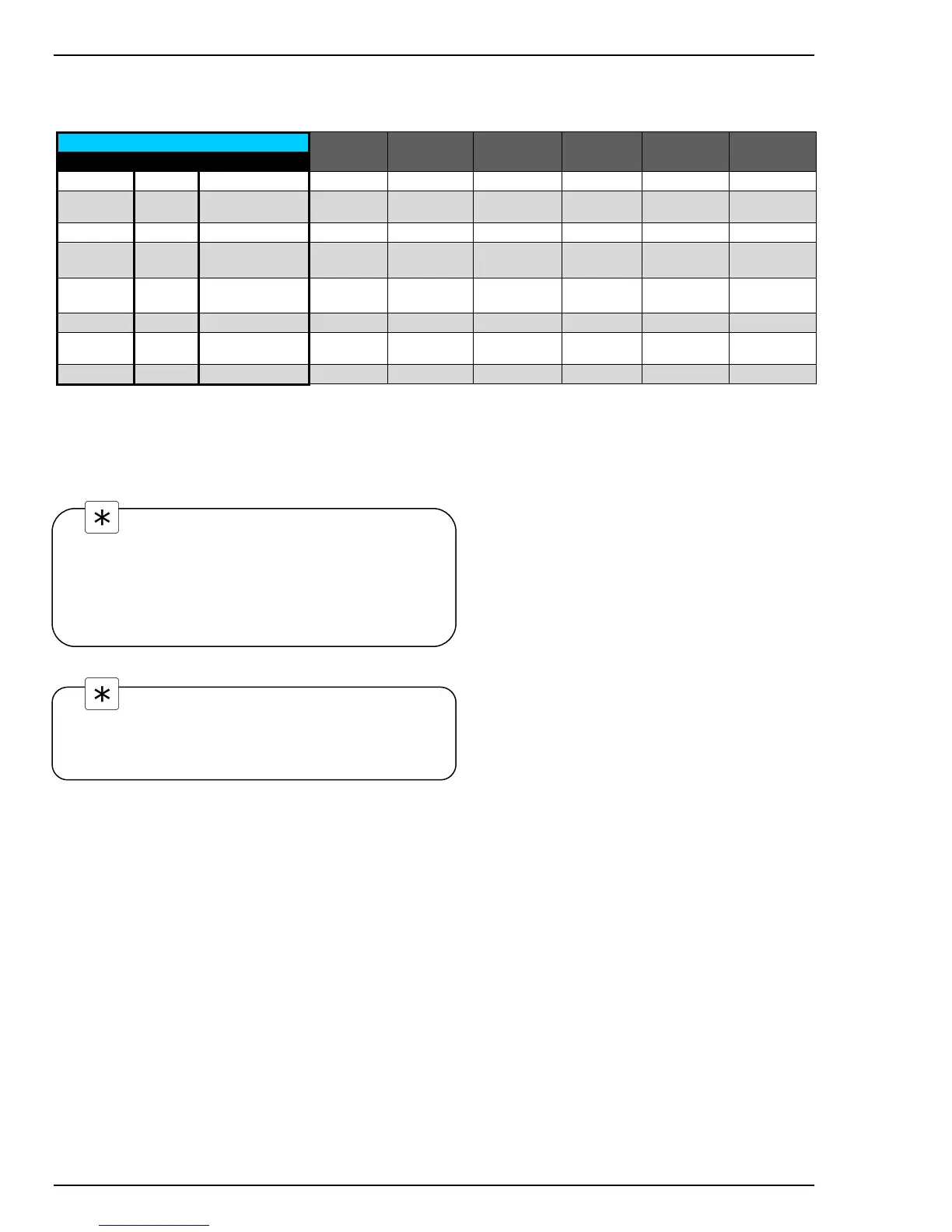
AP100, AP200, AP300 7660 and 7650 sensors have different color-coding in the cable assemblies than TB5 and TBX5
sensors. Use the table below to properly connect the sensor cable to the TB82PH.
TB82PH Terminal TB2
Color Number Description
ABB Models
TB5
ABB Models
TBX5
ABB Models
AP100
3
BB Models
AP200
ABB Models
AP300
ABB Models
7650/7660
Blue 1 Measuring electrode Blue
1
Blue Clear Clear Blue Clear
Yellow 2
Shield for measuring
electrode
None Yellow None None None None
Black 3 Reference Black
1
Black Black Red Black Black
Green 4
Solution (diagnostic)
Ground
None Green None Green/Yellow None None
Red
2
5 RTD Red
Red
Red Gray & Green Red
Red
4
(2 total)
White
2
6 RTD White White White White White White
Heavy Green 7 Shield (Screen) None
Heavy Green
(Shield)
None None None Yellow
None 8 Not Used None None None None None None
Notes:
1. BNC adapter required on sensors provided with BNC termination (See Figure 9).
2. Red and White wires not present on sensors sold without temperature compensators
3. Cut away and discard gray wire on AP100 sensors (if present)
4. Place both red wires in terminal 5
Note.
If an automatic temperature compensator is not used the
TB82PH must be configured for manual temperature
compensation. See the Configure Mode section for details.
Note.
TB5, AP100, AP300 and 7650/7660 sensors do not have a
solution ground rod required to fully utilize all the TB82PH
on-line sensor diagnostics. When configuring the
transmitter for use with these sensors the DIAGS
(diagnostics) choice must be set to OFF. See the
Configure Mode section for details.

 Loading...


