User's Manual | ACOM 2020S | 1.8-54 MHz Linear Power Amplifier
Page 26 of 76 | S e c t i o n INSTALLATION
c) Amplifier's RS-232 interface connector
Please, see Figure 2-3 | Amplifier rear panel - Connections, Pos. 2 and Table 2-4 | Signals and pin out of the
amplifier's RS-232 connector.
This connector may remain unused until you decide to control the amplifier remotely (see Section
6.2 Remote Control via RS-232 interface).
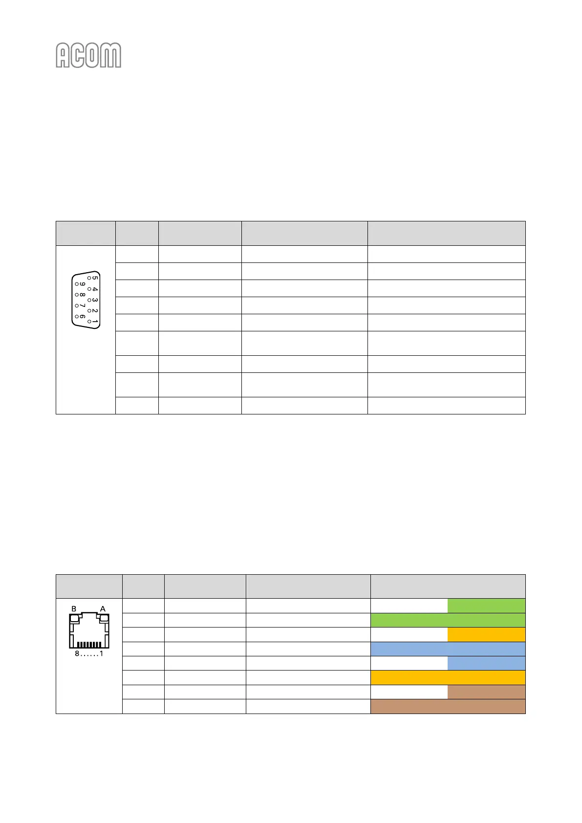
Table 2-4 | Signals and pin out of the amplifier's RS-232 connector
D-sub
connector,
9-pin, female
(Rear panel
view)
Data Set Ready /
Remote Power On
Clear To Send /
Remote Power On
Table 2-4 | Signals and pin out of the amplifier's RS-232 connector
d) RCU's LAN Ethernet interface connector
Please, see Figure 2-6 | RCU model R05 rear panel, Pos. 5 and Table 2-5 | Signals and pin out of the RCU's LAN socket.
This socket (RJ45 type) may remain unused until you decide to control the amplifier remotely via your local
network or via Internet.
You may select either Ethernet (cable connection) or Wi-Fi (wireless connection) interface to connect the
amplifier to your local network or to Internet (see Section 6.1 Remote Control via Ethernet Interface).
Automated software update process enables amplifier firmware download over Internet (see Section
7.5 Firmware).
Table 2-5 | Signals and pin out of the RCU's LAN socket
Colors (T568A pin assignment)
RJ45 socket,
8-pin, female
(Rear panel
view)
Table 2-5 | Signals and pin out of the RCU's LAN socket