3. FIRST POWER-ON, CONTROL SYSTEM, AND INITIAL CHECK
NOTICE
Do not turn the amplifier on for at least 2 hours after unpacking it in the room where it
will be used. Pay particular attention when you move it from a very cold into a warm
place - condensation is likely and this could result in damage to the high voltage circuits.
In such a case, wait at least 4 hours. A similar effect can occur after a rapid warming of
the operating room (for instance after switching on a powerful heater in a cold shack).
After following all instructions in Section 2 INSTALLATION, check whether the amplifier's rear panel mains
rocker switch is turned OFF (see Figure 2-3 | Amplifier rear panel - Connections, Pos. 3). Then insert amplifier's
mains plug into the wall outlet prepared for it. The amplifier remains switched off.
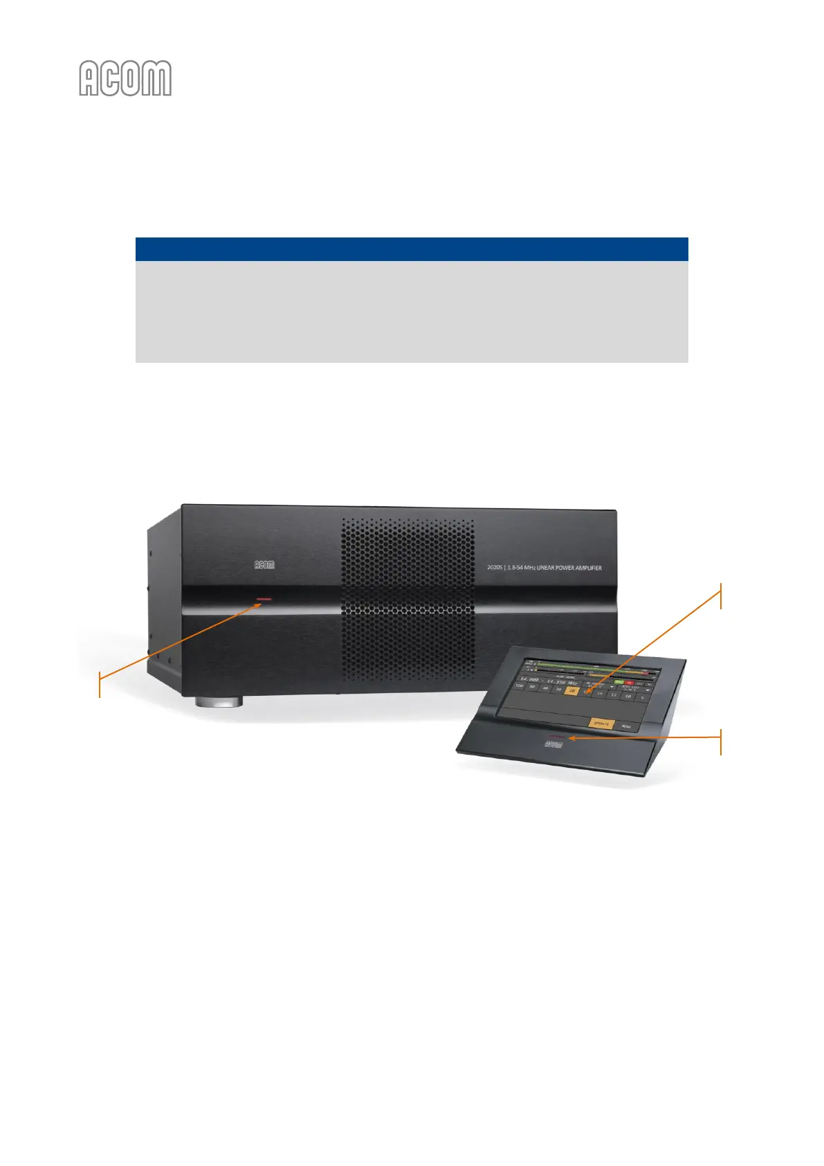
Figure 3-1 | Amplifier and RCU Front panels - Controls and Readouts
Figure 3-1 | Amplifier and RCU Front panels - Controls and Readouts
3.1. Low Energy STANDBY Mode of the Power Supply
Now you can turn on the amplifier's mains rocker switch (see Figure 2-3 | Amplifier rear panel - Connections,
Pos. 3). This will activate only the low-energy STANDBY mode of the amplifier power supply and the red LED
on amplifier's front panel will light up (see Figure 3-1 | Amplifier and RCU Front panels - Controls and Readouts,
Pos. (a)), as well as the red LED on RCU's front panel will light up also (see Figure 3-1 | Amplifier and RCU
Front panels - Controls and Readouts, Pos. (b)), while the amplifier's main power supply is still off and the RCU
display is dark (see Figure 3-1 | Amplifier and RCU Front panels - Controls and Readouts, Pos. (c)).