e) RCU's Wi-Fi device interface
Please, see Figure 2-6 | RCU model R05 rear panel, Pos. 6.
This interface may remain unused until you decide to control the amplifier remotely via your local Wi-Fi
network or via Internet.
You may select either Ethernet (cable connection) or Wi-Fi (wireless connection) interface to connect the
amplifier to your local network or to Internet (see Section 6.1 Remote Control via Ethernet Interface).
Automated software update process enables amplifier firmware download over Internet (see Section
7.5 Firmware).
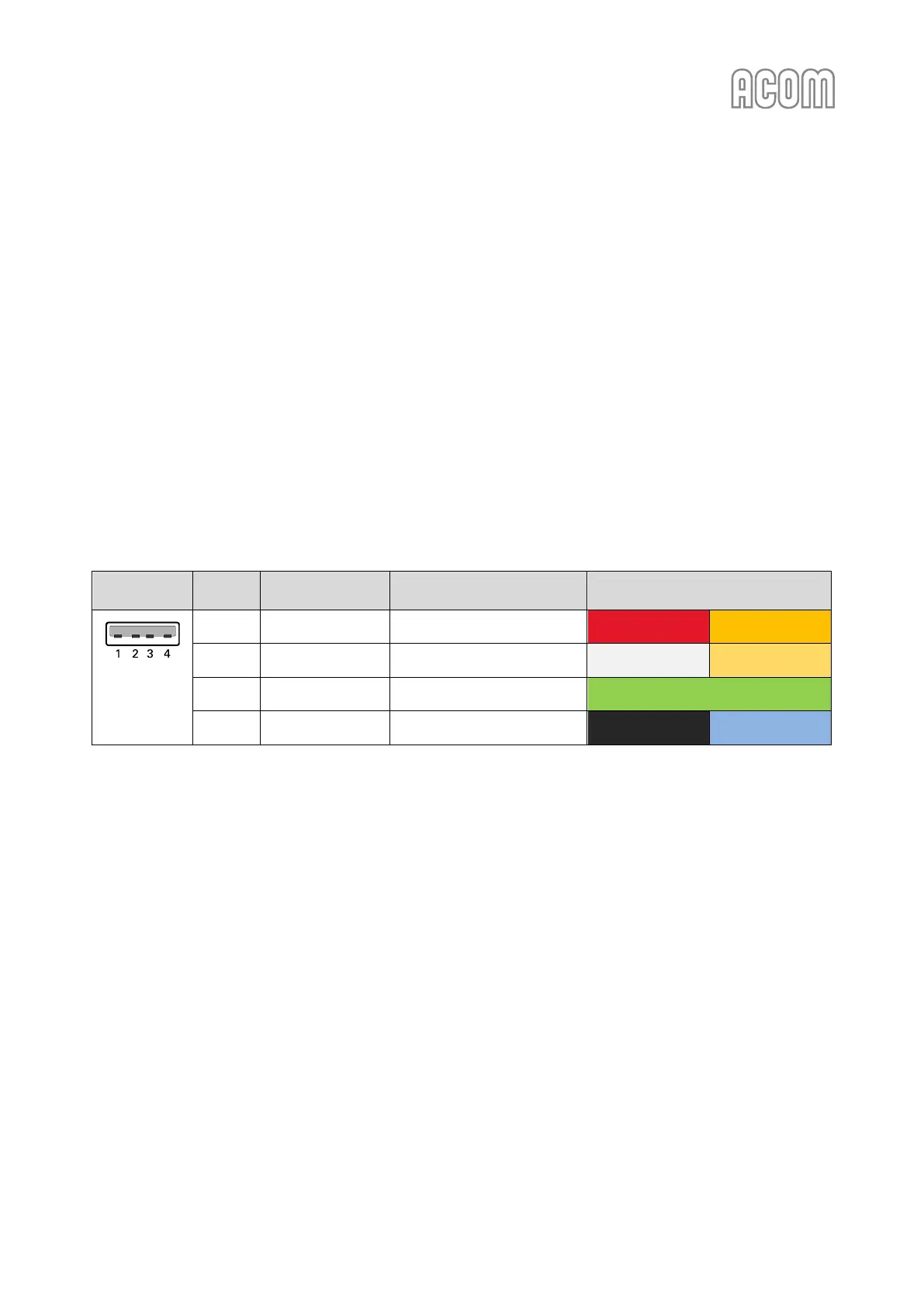
f) RCU's USB interface connector
Please, see Figure 2-6 | RCU model R05 rear panel, Pos. 7 and Table 2-6 | Signals and pin out of the RCU's USB
type A connector.
This connector (USB type A, female) may remain unused until you decide to update firmware of your
amplifier or to save Log Files to USB flash memory stick.
Please, see Sections 7.5 Firmware and 5.4 Menu FAULTS LOG.
Table 2-6 | Signals and pin out of the RCU's USB type A connector