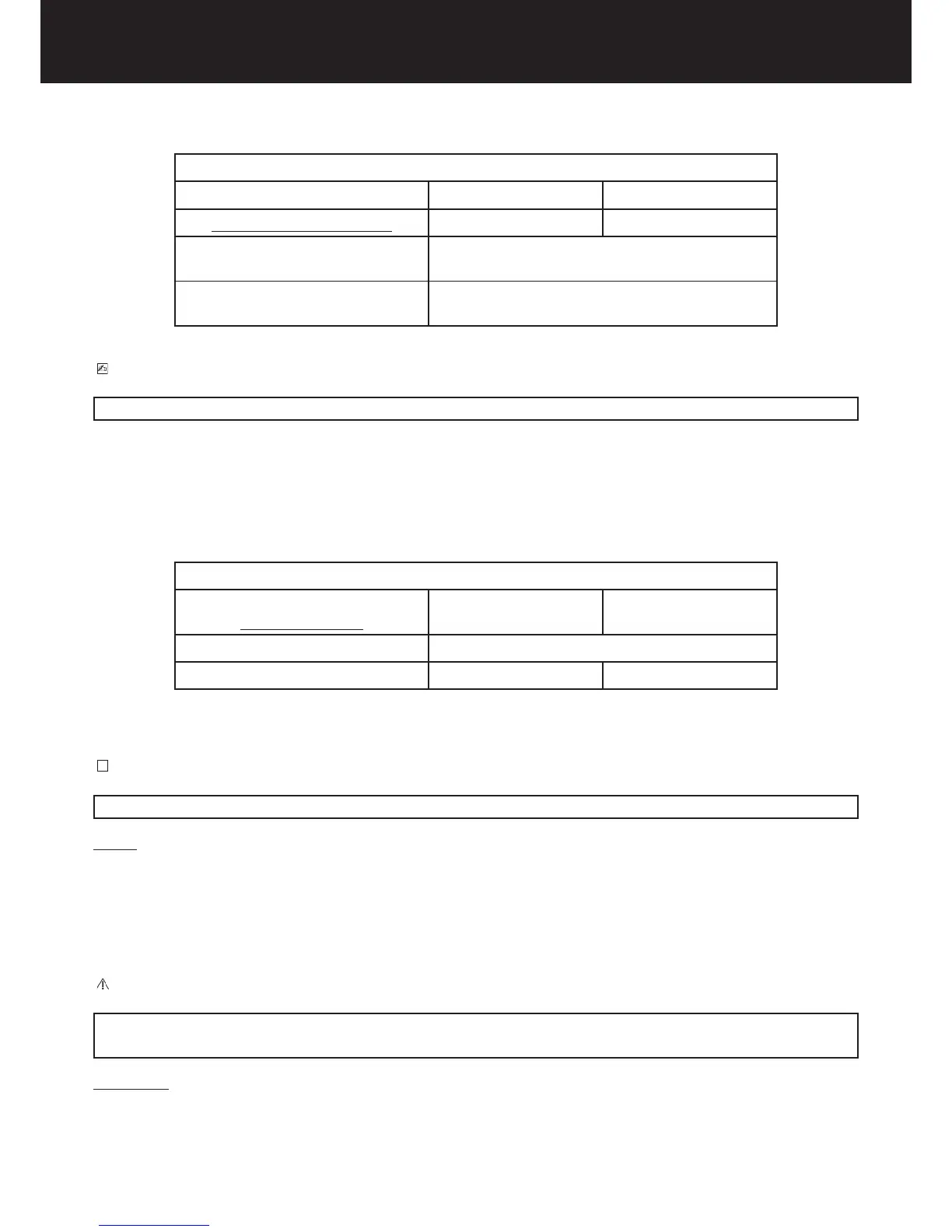
Chart B
MANUFACTURER’S RATING PLATE 230 V ± 10% 115 V ± 10%
POWER SUPPLY VOLTAGE 198 ≤ V ≤ 253 103,5 ≤ V ≤ 126,5
MINIMUM CONDUCTOR SECTION
MAXIMUM LINE LENGHT
1,5 mm2
10 m
MAXIMUM CONDUCTOR SECTION
MAXIMUM LINE LEGHT
2,5 mm2
20 m
PLEASE NOTE
For longer lines, the conductor section must be increased in proportion.
- The communication cables (C11, C12 – C21, C22) between the timer and the tubehead must be two-pole, twisted
and shielded with 0,25mm2 (es. tipo Belden 9501).
- The cables (S11, S12 – S21, S22) connecting the timer and the Rx signalling lamp for external use must be two-
pole type, of section 0,5mm2.
- The electric line characteristics must (Chart C).
Chart C
MANUFACTURER’S RATING PLATE
ELECTRICAL LINE
230 V ± 10% 115 V ± 10%
MAXIMUM VOLTAGE DROP 3 %
APPARENT LINE RESISTANCE 0,5 Ω 0,2 Ω
ELECTRIC CONNECTIONS
WARNING
Prior to installing the radiographic system, it is advisable that all the electric connections are arranged.
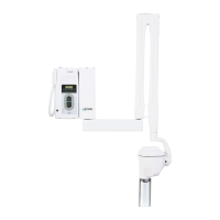
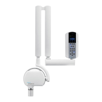
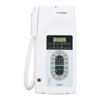
TIMER
On the timer installation wall, suitable runs for the following electric cables must be provided, according to the
installation electric diagram (refer to Chapter 15):
} timer electric cables;
} cables for the connection between timer and tubehead;
} cables connecting the timer and the X-ray signalling lamp for external use Xmind® LIGHT (OPTIONAL);
} cables connecting the timer and the remote control button Xmind® ECB (OPTIONAL).
CAUTION
According to the relevant standard, the timer must be installed in a position that allows the operator to permanently control the radiographic
exposure.
TUBEHEAD
On the wall plate installation wall, a suitable run for the cable connecting the timer and tubehead must be
provided.