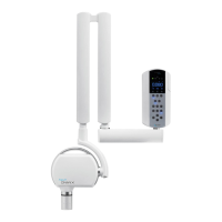
ASSEMBLY INSTRUCTION (refer to Fig. 10 - 11)
1. Take out the timer out of the packaging and take out the drilling template 1.
2. Position the drilling template 1 on the radiographic system installation wall, at the required height.
3. Fix the template 1 with adhesive tape.
4. Check the holes for uprightness and alignment with the oor, using a plumb line.
5. Mark the timer xing holes on the wall using the drilling template.
6. If required, mark the holes for the electric cables connecting the timer to tubehead.
7. Drill using a Ø3 tip, then drill again with a Ø6 tip to prevent any aking of the white coat.
8. Remove the template 1 and insert the suitable anchor screws provided 2.
9. Open the timer by unscrewing the three screws 8.
10. Withdraw the 26-pole connector from its seat to release both timer guards.
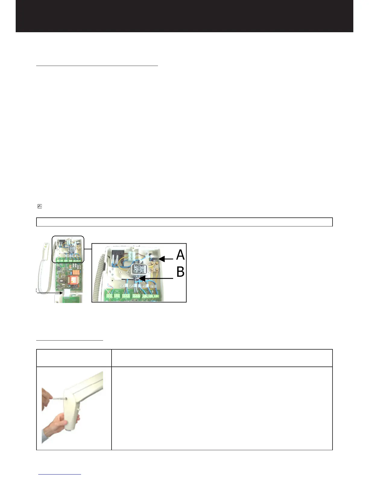
11. Approach the timer 8 to the wall and insert the electric feeding cables into the slot A or the slot B.
12. Insert the connection cables coming from the tubeheads into the slot A or the slot B: when the timer is ins-
talled aside the wall plate insert in between the rubber cover for the electrical cable.
13. Insert the cables of the X-ray signaling lamp for external use (OPTIONAL) and the cables of the remote
control button (OPTIONAL) into the slot A or the slot B.
14. Approach the timer base 8 to the wall, matching the three anchor screws with the holes screw the screws
with the relevant washers.
PLEASE NOTE
The use of the slots A or B for the cables is arbitrary; use the slots which adapt better to the specic conguration of installation.
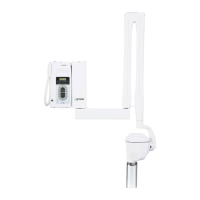
4.7. ASSEMBLING THE TUBEHEAD
ASSEMBLY INSTRUCTION
1. Take out the tubehead from the packaging.
2. Check that all the rating data match the power supply voltage.
3. Remove both guards from the pantograph type arm by loosening the relevant
screws.