10 80-0180-307, Rev A
NOTE: Step 6 is performed to configure a Model 3090-01 for a RIM
exit device using 8700/8800 Exit Devices.
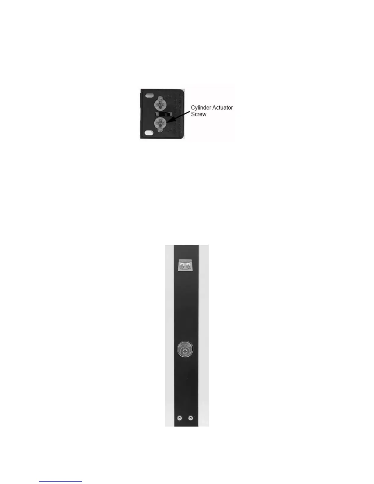
6. On the back side of the exit device, REMOVE only the lower Phillips
head screw, depending on hand of door, to free up the cylinder
actuator for use (see Figure 11).
Figure 11
NOTE: Steps 7–8 are performed to configure a Model 3090-02 for a
MS 1850 application using a MS
®
series Deadbolt.
7. For MS Deadbolt, INSERT cam plug into lock case ensuring the
notch on the cam plug is aligned with lock case set screw.
NOTE: Cam Plug must be positioned below door surface.
8. TIGHTEN set screw and SECURE with the two (2) brass cam plug
screws (see Figure 12).
Figure 12
 Loading...