12 80-0180-307, Rev A
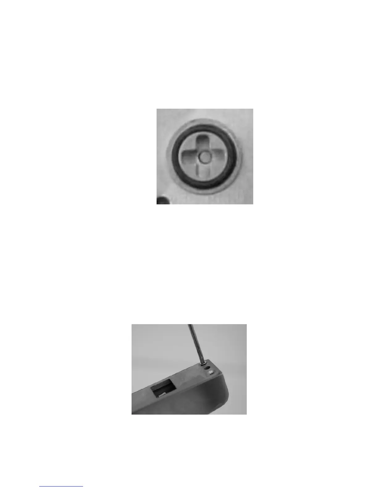
NOTE 1: Hubs that have (+) shape are for use with deadlatches and
exits only.
NOTE 2: Hubs that have (-) shape are for use with deadbolts only.
3. To change rotation and reconfigure the unit to the opposite rotation,
INSERT a flat screwdriver into the output hub (see Figure 14)
located on the back of the eForce 150, and TURN approximately
270° clockwise or counter-clockwise.
Figure 14
Installing the Mortise Cylinder
CAUTION
There are wires connecting the housing and back plate assembly.
These must be handled with care to not cause damage. Over-
tightening must also be avoided.
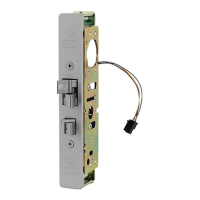
1. Using a Philips head screwdriver, REMOVE the eight (8) #10-32 x
5/8” screws on the back of the eForce 150 (see Figure 15), and
gently LIFT the back plate off the housing.
Figure 15