Chapter 8 Maintenance & troubleshooting
57
Osmo1® Single-Sample Micro-Osmometer User Guide
4. Remove the Fuse Holder; then remove the two fuses.
5. Insert two replacement fuses into the Fuse Holder
(Figure 87).
NOTE: Use replacement fuse P/N 70011:
Fuse, 1.0A 250V SB 5 x 20 mm.
NOTE: Double-check the values marked on the new
fuses before you install them. The instrument
automatically adjusts for voltages between
100 VAC and 240 VAC, but appropriately rated
fuses must be installed.
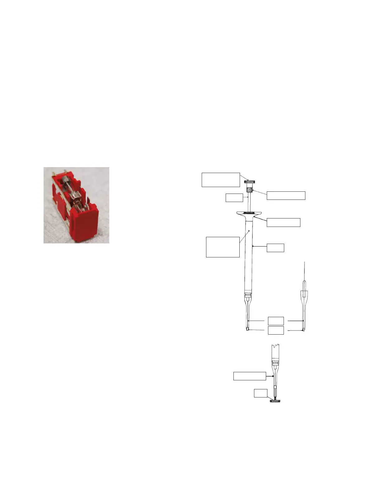
Figure 87: Fuses in Fuse Holder
6. Re-install the Fuse Holder into the back of the
instrument.
7. Close the Fuse Holder Door.
8. Reconnect the power cord to the Osmo1 and plug it
into an outlet.
9. Power on the Osmo1.
Sampler plunger wire replacement and verification
To ensure proper instrument operation, you should
replace the sampler plunger wire every 500 tests (or
each time you empty a Micro-Sample Test Kit).
NOTE: A sampler plunger wire is included with each
Micro-Sample Test Kit.
Failure to replace the plunger wire may aect instrument
accuracy and repeatability.
NOTE: Refer to Figure 88 when completing the sampler
plunger wire replacement procedure.
Calibration
gauge & key
Shaft bushing
Shaft
Finger grip
Body
Calibration
set-screw
access
Sampler tip
Key
Wire
Tip
Figure 88: Sampler plunger