PPC-3150/3170 User Manual 10
2.1 Quick Installation Guide
Before you start to set up the panel PC, take a moment to become familiar with the
locations and purposes of the controls, drives, connectors and ports, which are illus-
trated in the figures below.
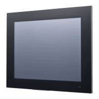
When you place the panel PC upright on the desktop, its front panel appears ass-
hown in Figure 2.1.
Figure 2.1 Front Panel
1. (Network status LED) LAN LED
2. (HDD status LED) HDD LED
3. (Power status LED) POWER LED
Status
LAN LED
HDD LED POWER LED
LAN1 LAN2
Power off
(S5)
Off Off Off Off
Power on
(S0)
Yellow
(Operating, blinking)
Green
(Operating, blinking)
Yellow
(Operating, blinking)
Green