12
SYSTEM LAYOUT MENU
NOTE: the rst page of this menu represents the home screen of the
applicaon;
A
B
C
D
E
F
G
H
I
L
M
N
O
P
Q
R
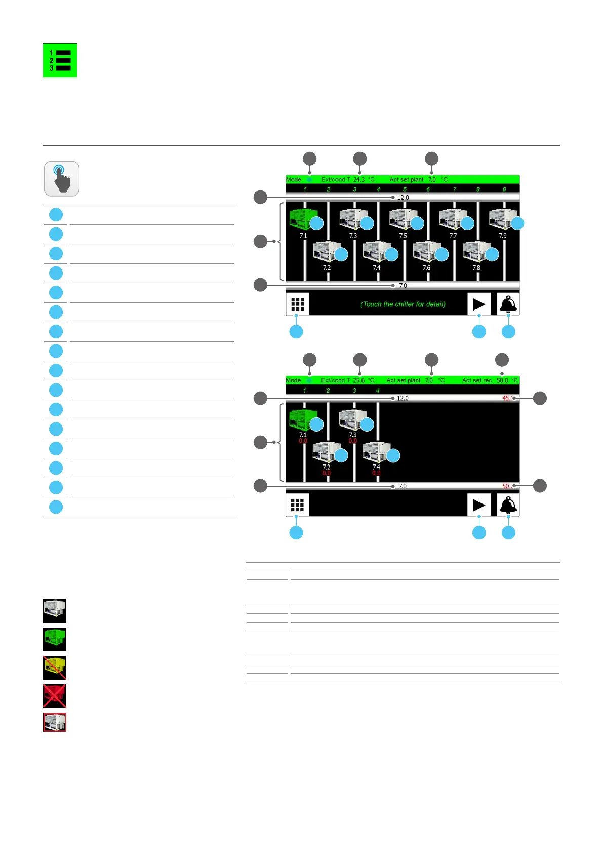
SYSTEM LAYOUT - Chiller main monitor (HOME)
Index Meaning
1 Indicates the current functioning mode: cooling (d) or heating (j)
2
Current temperature value detected by the NTC probe connected to output U1 on the Multichiller-
Evo board. This probe must be installed outdoors in case of Air/water chiller or on the source return
in case of Water/Water chiller
3 Current temperature value set as work set
4 Current temperature value read by the NTC probe connected on the pCOe board input B1
5 Current temperature value read by the NTC probe connected on the pCOe board input B2
6
Each image displays one of the units currently controlled by the MULTICHILLER-EVO accessory. The
water value produced from the system side (white) and recovery unit side (red, only on multipurpo-
se units) is associated with every image
7 Current temperature value set as recovery side set
8 Current temperature value read by the NTC probe connected on the pCOe board input B3
9 Current temperature value read by the NTC probe connected on the pCOe board input B4
ACTIONS
AVAILABLE:
ATTENTION:
1
4
A B C
2 3
5
D
E
F
G
H
I
L
M
N
1
A B C
2 3
O
P
Q
7
8
9
R
6
4
5
6