35
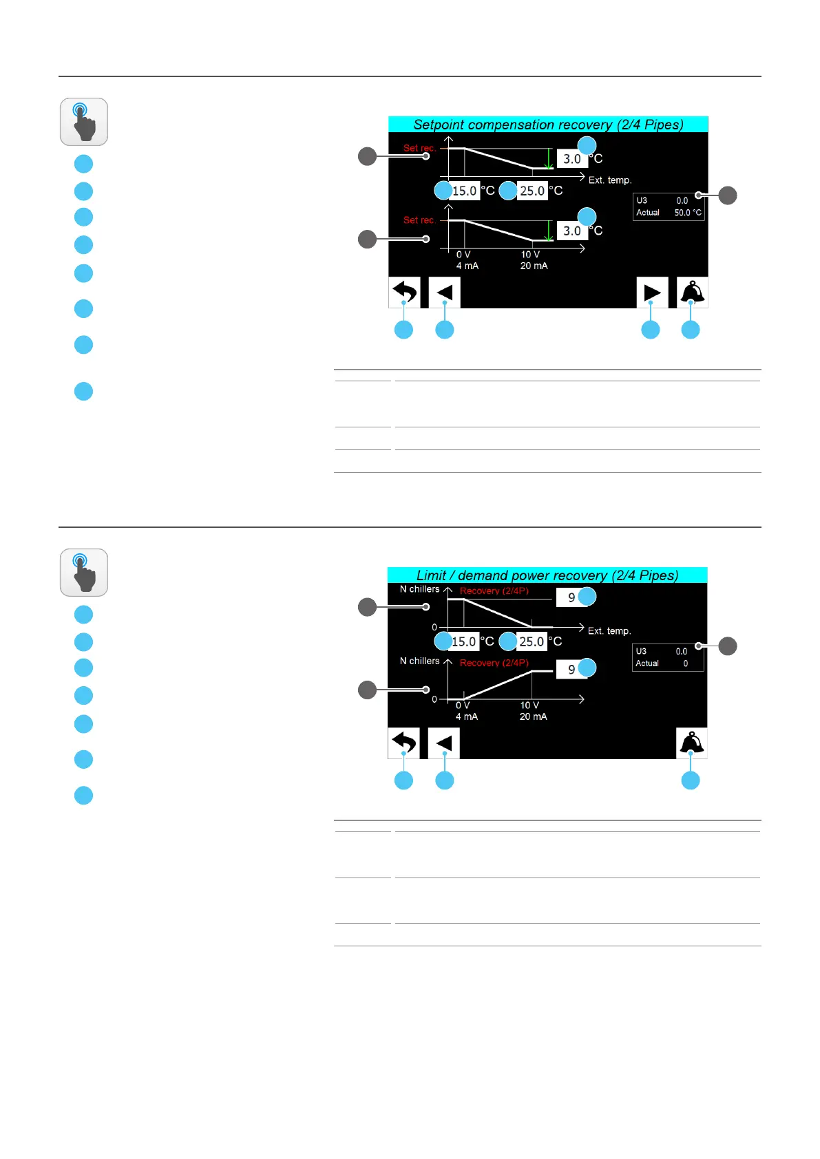
INSTALLER - Remote control - Recovery side set point compensaon sengs
A
B
C
Index Meaning
1
Indicates the chart that summarises the functioning of the climatic curve applied to the recovery
side set; setting at which outdoor air temperature (read by the NTC probe connected to the multi-
function input duly set) the recovery work set remains unchanged and at which it is decreased and
by how much
2
Indicates the chart that summarises the functioning of the climatic curve applied to the recovery
side set; setting the decrease to be applied to the heating set at maximum of the input signal
3
Indicates the value read by the device connected to input U3 and the set resulting from correction
according to the curve described
ACTIONS
AVAILABLE:
1
A B D
2
D
E
F
C
3
G
G
E
F
H
H
INSTALLER - Remote control - Power demand/limitaon sengs on recovery side
A
B
C
Index Meaning
1
Indicates the chart representing the power demand or limitation (if selected as function on the U3
input, with temperature variation) according to the temperature read by the NTC probe connected
to the U3 input; the chart shows the temperature at which no chiller is active, and the one at which
to activate the maximum number of chillers specied for the recovery mode
2
Indicates the chart representing the power demand or limitation (if selected as function on the U3
input, with voltage or current signal) according to the U3 input signal value; the chart shows the
values at which no chiller is active, and those at which to activate the maximum number of chillers
specied for the recovery mode
3
Indicates the value read by the device connected to input U3 and the maximum number of chillers
that can be activated at that time
ACTIONS
AVAILABLE:
1
A B C
2
D
E
F
3
G
F
D
E
G