38
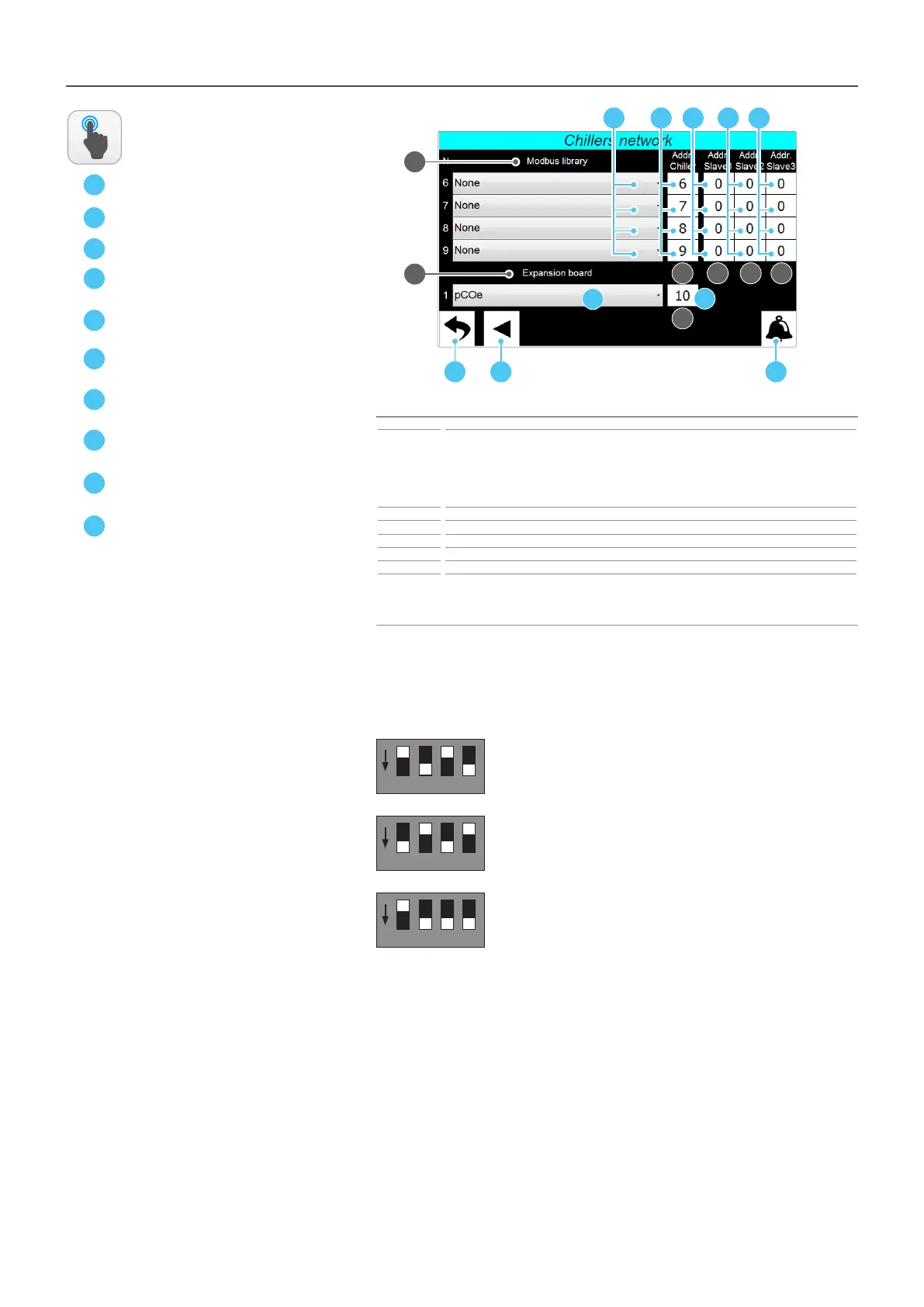
INSTALLER - Chillers network - Set of the connected chillers (Page 2)
A
C
Index Meaning
1
Indicates the modbus library used to communicate with the network chillers; the number on the
left indicates the chiller to which we refer. If you want to add a chiller, you must specify the correct
library to be used for serial communication. However, if a chiller is added at a later stage, the overall
management needs to be “xed threshold” since, in order to use the optimised managements, it is
necessary to load the specic data of the units on the Multichiller-Evo (for more information, contact
the after-sales service/assistance)
2 Indicates the modbus address to be assigned to each chiller
3 Indicates, only for the NSM units working in master/slave mode, the chiller slave 1 address
4 Indicates, only for the NSM units working in master/slave mode, the chiller slave 2 address
5 Indicates, only for the NSM units working in master/slave mode, the chiller slave 3 address
6 Species whether the pCOe expansion board is present
7
Indicates the Modbus address assigned to the pCOe board. The address assigned to the pCOe board
must match the one set on the same board via dipswitch. By default, the dips on the board are set to
assign the pCOe address 10, however, if desired, you can modify it with a value between 1 and 15, by
properly modifying the dips on the pCOe board
ACTIONS
AVAILABLE:
B
D
E
F
G
H
1
D
A CB
E F G H
2 3 4 5
7
6
I
L
1 2 4 8
ON
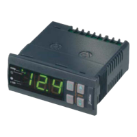
ATTENTION: the dipswitches on the pCOe used to set the serial address made up of 4 “wei-
ghed” dips; the value assigned to the serial address of the pCOe board will be equal to the
sum of the acve dips values (to acvate a dip it is necessary to move it down); below are
some examples:
2 + 8 = pCOe address: 10 (default)
1 2 4 8
ON
1 + 4 = pCOe address: 5
1 2 4 8
ON
2 + 4 + 8 = pCOe address: 14
I
L