12 ± 2% SAT
Position of C.G. in flight …………………….. 20 ÷ 30% SAT
1.5.6 Operating limitations
Refer to the Aeroplane Flight Manual ( AFM ), Section 2 for more details about the
following operating limits:
- Airspeed limits,
- Weights limits,
- C.G. range limits,
- Approved manoeuvres.
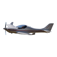
1.6 Technical description of the aeroplane
1.6.1 General
An airframe consists of a sandwich shells from advanced composite material. The
shell is of three layer construction. The external and internal shell layers are made of a
glass and a carbon fiber fabricses, which are saturated with a resin. Between them
there is a filling from a hard foam panels. The shells are formed in negative forms and
they are heat treatmented 12 hours at temperature 54 °C for resin-harden.
1.6.2 Fuselage
The fuselage sandwich shell is divided in the symmetry plane. The fuselage cross-
section are parabolic curves. The cockpit is reinforcemented with hollow profile from
advanced composite material. The back rest of the crew and the central pedestal are
glued and together with the shells they create reinforcement element of the airframe.
The fin is made together with the fuselage. The wing central panel is fixed at the
fuselage. There is the integral tank in the forward box of the wing central panel. The
back box of the wing central panel is used as room for main legs of the retractable
undercarriage. There are stiffening ribs in the back box of the wing central panel for
gripping of the legs of the fixed undercarriage. A rescue system with ejection of the
rescue parachute through removable cover may be located behind the fire wall of the
power plant. A horizontal tail is fixed at the fuselage too. The baggage compartment is
situated behind the seats. There is the frame with the access hole into the rear part of
the fuselage. The Perspex canopy is glued on the composite frame. The canopy is
attached to the nose section of the fuselage by pins which make it possible for the
canopy to be tilted forward. For easier manipulation, the weight of the canopy is
counterbalanced by two gas struts which allow it to open effortlessly. The engine
section in the nose is separated from the cockpit by a firewall which the engine bed is
attached to.
Date: