TECHNICAL DESCRIPTION, OPERATING, MAINTENANCE AND REPAIR MANUAL
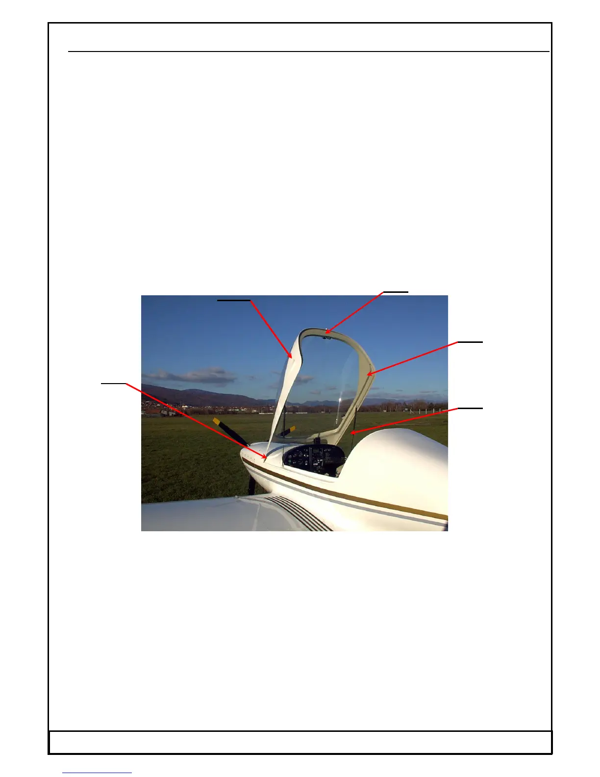
1.6.7.2 Cockpit canopy
The cockpit canopy consists of one part. The Perspex canopy is glued on the
composite frame. The canopy is attached to the nose section of the fuselage by two
pins (B) which make it possible for the canopy to be tilted forward. For easier
manipulation, the weight of the canopy is counterbalanced by two gas struts (GF)
which allow it to open effortlessly. On the lower frame there are handles outside the
canopy. The canopy is equipped with a lock on the upper rear section of the frame.
The ventilation air flows through the canopy frame (HR) which is shaped as a hollow
laminated profile. The air inlet for the ventilation (AO) is located on the upper rear
section of the canopy and serves as the handle for the opening and the closing of the
cockpit canopy. The ventilation air is led through the hollow to the adjustable
venting nozzles on both cockpit sides. The side sliding window is located on the left-
hand side of the canopy. The cockpit canopy close (HV) finds in the symmetry plane
of the fuselage. This close is accessible from both seats. The pin of the close is
created as the latch with push spring.
The lock with the key which is located beside the close allows the locking of the
canopy cockpit.
1.6.8 Equipment
1.6.8.1 Seats and safety harness
The safety belts – 4 point static harness restrain system is attached to the left and
right seats side panel and to the strut behind the back supporter of the seats.
1.6.8.2 Baggage compartment
The baggage compartment is situated behind the back supporter of the seats and
separated from the rear fuselage section with the frame.
There is a well in the baggage compartment. An elevator control rod and a rudder
control rod as well as a control of the main undercarriage brake passes through this
well. Maximum baggage weight is stated on a placard stick near the compartment. A
loading of the baggage compartment have to be in accordance with a balancing of the
aeroplane.
Date: