TECHNICAL DESCRIPTION, OPERATING, MAINTENANCE AND REPAIR MANUAL
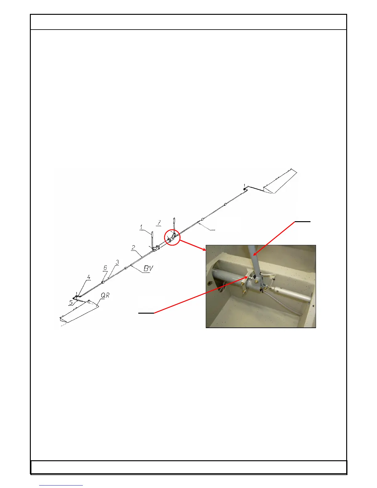
1.6.9.2 Lateral control system
A control stick lateral motion (1) is transferred by rod (2) into a pin joint (BV), which
allows a disconnection of the rod in case of a derigging of a wing. An access to this
joint (BV) is allowed through an access hole at a model with a fixed undercarriage and
through a main wheel well at a model with a retractable undercarriage.
Long rod (3) guides from the end of the wing central panel to the two-arm lever (4),
which a console with the bearings is attached at the wing main spar. This lever provides
a necessary differentiation of the aileron deflections. Two-armed lever angular
displacement is transferred at aileron by short rod (5). A longitudinal movement of a
short rod is transferred into an aileron root rib, which a point of rotation is below a
upper surface wing. The long rod (3) is guided in a sliding guide rollers (6) which are
located in the wing root rib and in the wing auxiliary rib. Its guide surfaces are
equipped with a riveted sliding capsulars on a rod. The range of the control stick
deflection is adjusted by stops (AS) on the consoles of the torsional tube (TR). The
stops are screws type with the fastening nut.
Fig.13 Lateral control system scheme.
1- Control stick,
2- Rod in the wing central panel,
3- Rod in the wing,
4- Two-arm lever,
5- Aileron rod,
6- Sliding guide rollers,
7- Sliding bearings
BV- Split pin joint,
QR- Aileron
AS- control stick adjustable stop
Date: 01.03.2002 WT-9 Dynamic Section 1 Page 1 - 20
BV