TECHNICAL DESCRIPTION, OPERATING, MAINTENANCE AND REPAIR MANUAL
3.11 Control surfaces deflections setting
Control surfaces deflections of a new aeroplane are set by the manufacturer.
Deflections are adjusted at values specified in Control Surfaces Deflections Record
enclosed in this Manual.
A neutral position of control surfaces and controls is a base for adjustment of
deflections.
3.11.1 Aileron deflections adjustment ( see Lateral control system scheme, page 1-20 )
The range of the control stick deflection is adjusted by stops (AS) on the consoles of
the torsional tube (TR). Aileron deflections can be adjusted with adjustable threaded
end of a short rod (5). Further adjustable rode ends are located at a place a pin joint
(BV), which allows a disconnection of the rod in case of a derigging of a wing. An
access to this joint (BV) is allowed through an access hole at a model with a fixed
undercarriage and through a main wheel well at a model with a retractable
undercarriage.
Deflection of the two-arm lever (4) , which a console with the bearings is attached at
the wing main spar and provides a necessary differentiation of the aileron deflections,
is set by the manufacturer and can not be adjusted in operation.
3.11.2 Elevator deflections adjustment ( see Longitudinal control system scheme, page 1-19 )
The control stick motions are limited by two stops (7). A “push-down” stop is glued
into the wing central panel main spar. A “pull-up” stop is on the lateral located tube,
which is passed through the walls of the middle console between the seats. An
adjustment of the stops is allowed after removal of the pedestal upper cover. Elevator
deflections can be adjusted with adjustable threaded rod end (2).
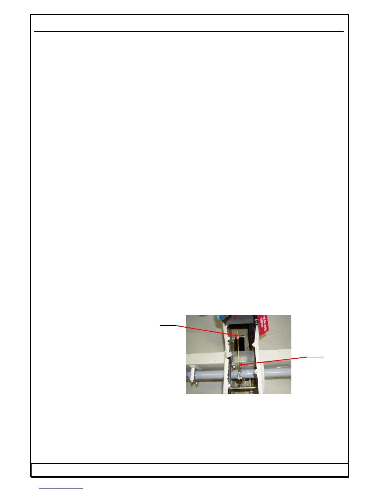
3.11.3 Trimming deflections adjustment
A neutral position of a trim control lever can be adjusted by means of a adjustment of a
length of the rod (R). An adjustable nut (N) is accessible after removal of the tunnel
upper cover between seats.
Fig. 29 Trimming deflection
adjustment
3.11.4 Flap deflections adjustment
Set flap position is locked by the deflection of the flap control lever into the appropriate
recesses on the pedestal cover, where a lever is pushed by a spring.
A neutral position of each flap adjusts by means of an adjustment of an adjustable short
rod end (6). A common neutral position of the flaps can be adjusted by means of an
adjustment of an adjustable rod end (3). An access to this joint is allowed after removal
of the pedestal upper cover between seats.
Date: 01.03.2002 WT-9 Dynamic Section 3 Page 3 - 20