TECHNICAL DESCRIPTION, OPERATING, MAINTENANCE AND REPAIR MANUAL
1.6.10.5 Engine cowlings
There are two laminated cowlings. The disassembly of a upper cowling is easy, just
release the quick-closing locks. The quick-closing locks releases by means of a
suitable screwdriver with a 90° counterclockwise slewing. The releasing starts at a rear
corner with the simultaneous raising of the cowling. The quick-closing locks releases
have to remain over a cowling until the disassembly of a all cowling.
The lower cowling is removed after unscrew the attachment screws connecting the
cooler to the cowling face side, then unscrew the attachment screws connecting the
cowling to the firewall border. The coolers remain connected with the inlet hoses.
1.6.10.6 Engine lubrication system
The ROTAX 912 engine is provided with a dry sump forced lubrication system. The
oil pump is driven by the camshaft. The oil pump sucks the motor oil from the oil tank
via the oil cooler and forces if through the oil filter to the points of lubrication in the
engine.
The surplus oil emerging from the points of lubrication accumulates on the bottom of
crankcase and is forced back to the oil by the blow-by gases. The oil tank is equipped
with a venting hose. The oil temperature sensor for reading of the oil inlet temperature
is located on the oil pump housing.
Refer to the Operator’s Manual for all versions of ROTAX 912 for additional
information.
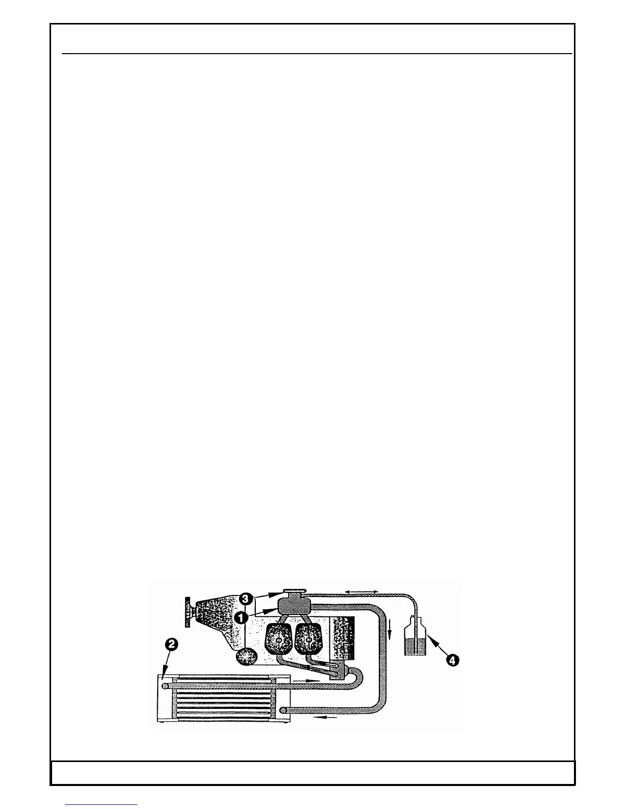
1.6.10.7 Engine cooling system
The cooling system of the ROTAX 912 engine is designed for liquid cooling of the
cylinder heads and ram-air cooling of the cylinder. The cooling system of the cylinder
heads is a closed circuit with an expansion tank and with a overflow bottle. The
coolant flow is forced by a water pump, driven from the camshaft, from the radiator to
the cylinder heads.
From the top of the cylinder heads the coolant passes to the expansion tank (1). Since
the standard location of the radiator (2) is below engine level, the expansion tank
located on top of the engine allows for coolant expansion. The expansion tank is
closed by a pressure cap (3) ( with excess pressure valve and return valve ). At
temperature rise of the coolant the excess pressure valve opens and the coolant will
flow via a hose at atmospheric pressure to the transparent overflow bottle (4). When
cooling down, the coolant will be sucked back into the cooling circuit.
A direct reading of the coolant temperature is not taken. The coolant temperatures are
measured by means of temperature probes installed in cylinder heads. This system
allows for accurate measurement of engine temperature, even in event of fluid loss.
Fig. 20 Engine cooling system
Date: 01.03.2002 WT-9 Dynamic Section 1 Page 1 - 27