TECHNICAL DESCRIPTION, OPERATING, MAINTENANCE AND REPAIR MANUAL
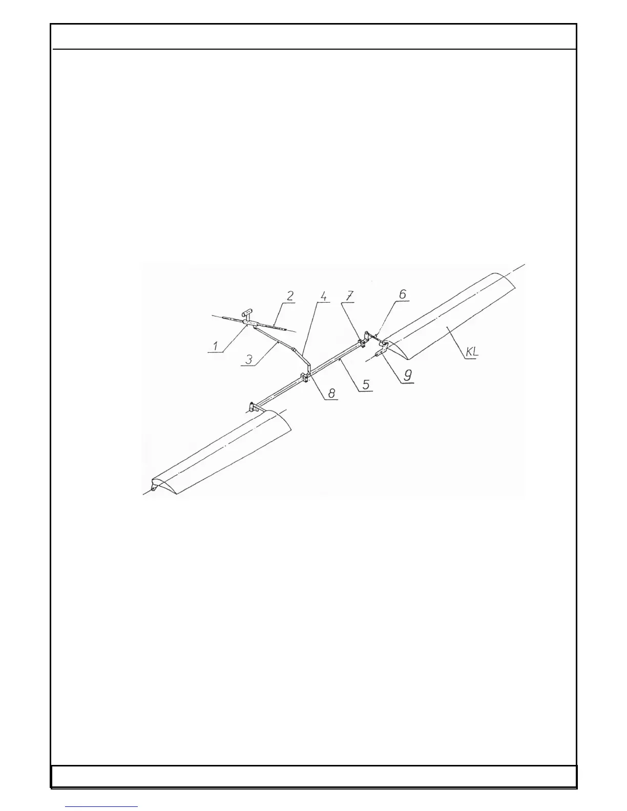
1.6.9.3 Wing flap control system
The wing flaps are controlled by a flap control lever (1) located on the pedestal
between the seats.
Set flap position is locked by the deflection of the flap control lever into the appropriate
recesses on the pedestal cover, where a lever is pushed by a spring.
The lever deflection is transferred at a longitudinal movement of a rod (3) to the
torsional tube (5), which transfers this motion symmetrically on both wing flaps. The
torsional tube (5) is supported at three sliding bearings (7). Two short rods (6) with the
adjustable rod ends provide for a connection of the torsional tube with the wing flaps.
These adjustable rod ends allow the symmetrical deflections adjustment of both flaps.
The rods (6) are jointed with the flap control lever by means of the disconnection pin,
which is secured by a cotter pin. An access to this joint is allowed by the wing flap
deflection into the maximum lower landing position.
Fig. 14. Wing flap control system scheme
1- Flap control lever,
2- Changing gate,
3- Rod,
4- Arm of the torsional tube,
5- Torsional tube,
6- Short rod,
7- Sliding bearing,
8- Arm joint bolt,
9- Flap arm,
KL- Flap
Date: 01.03.2002 WT-9 Dynamic Section 1 Page 1 - 21