TECHNICAL DESCRIPTION, OPERATING, MAINTENANCE AND REPAIR MANUAL
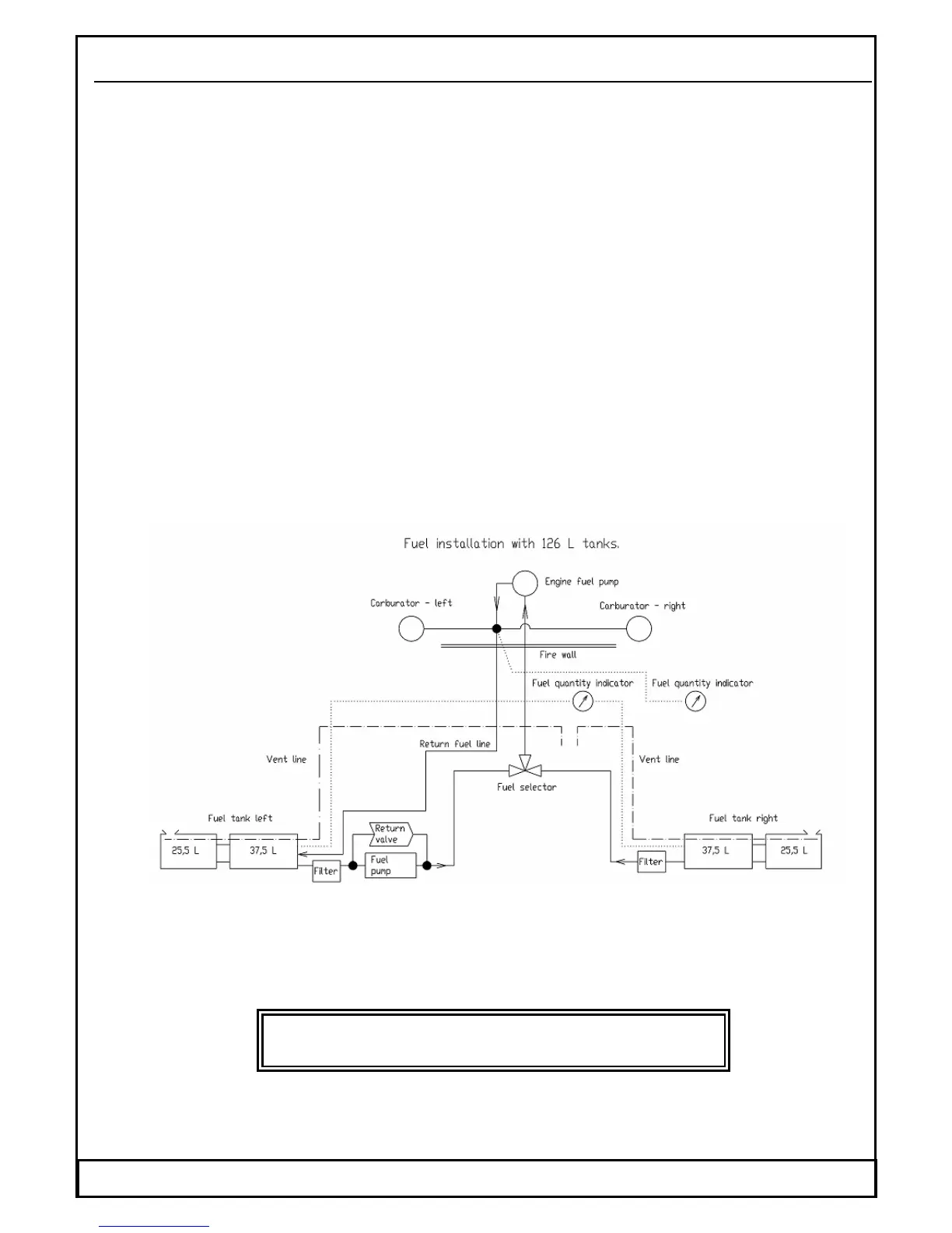
1.6.10.8 Aeroplane fuel system
The integral fuel tanks are located in the forward box of the wing central panel and
optionally in wings. The tanks are connected with simple hose joint with clamps.
There is a large diameter houe, wich serves for fuel flow from wing tank to central
section tank, on the top side are two small diameter hoses, first of them for ventig line
and second to join the free air of both tanks. The inner walls of the integral fuel tanks
are paint by a special resin with a less electrical resistance. There is a bulkhead in each
tank for the preclusion of a rapid fuel flowage during the flight manoeuvres. The total
fuel tankage is 75, optionally 125 litres. The fuel tank filler necks are placed on a wing
upper surface.
The fuel is feeded from the fuel tank into the fuel cock (shut-off cock of fuel also)
through the fuel filter into the engine fuel pump. From the pump fuel passes into the
two carburettors. Through a return line surplus fuel flows back to the left fuel tank.
The vent pipe is outgoing from the upper part of the fuel tank, proceeds along the fire
wall and the vent opening is located at a lower surface of the fuselage behind the fire
wall. The electrical fuel indicator switch allows the indication of the fuel quantity in
the left or the right fuel tank. Yellow light annunciator above the fuel indicator will be
illuminated with the remaining fuel of 7 litre in each fuel tank. Each fuel tank is
equipped with the draining outlet on the wing lower surface.
When filling the 125 litres fuel tank there is necessary to let the fuel flow into central section tank.
The diameter of connectiong house is not large enough to fully fill the central section tank during
refueling.
After each refuelling check the fuel level in tanks.
WARNING
Do not manipulate with open fire during refuelling or draining.