TECHNICAL DESCRIPTION, OPERATING, MAINTENANCE AND REPAIR MANUAL
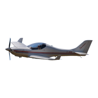
1.6.3 Wing
A construction of the wing is two – box type ( the main spar caps are made from the
carbon rods and one auxiliary girder ). A torsion box is glass fibre reinforced plastics
sandwich construction. Optionaly is in the front wing part installed integral fuel tank
which is connected with central section fuel tank with simple house connection with
clamp. The spars of right and left wings are joined to the wing central panel spar with
the help of two pins. The outer pin is inserted through the room for main legs of the
retractable undercarriage ( at model SPEED ) or through the access hole on the lower
wing surface ( at model CLUB and TOW ). The inner pin is inserted through the hole
in the cockpit below pilot seat. The third join point is the pin of the auxiliary girder.
The Pitot-static head is located on the right wing leading edge.
1.6.3.1 Aileron
A construction of the aileron is the sandwich shell structure type. The aileron is
attached to the upper surface of the wing shell with three hinges from advanced
composite material. The movement by means of the rod is transmitted into the root rib.
The control-surface weight balance is attached on the aileron tip rib. The deflections of
the ailerons are differentiated 1: 1,6 .
1.6.3.2 Wing flap
The wing flap is the slotted flap type, with the low lying point of rotation. A
construction of the wing flap is the sandwich shell structure type. The flap is attached
to the wing with four hinges. The movement by means of the rod is transmitted into
the wing flap root rib. The flap control lever has four positions: retracted, take-off
with flap deflection 15°, landing position with flap deflection 24 ° and landing
position with flap deflection 35°.
1.6.4 Horizontal tail unit
The horizontal tail unit consists of a stabilizer and elevator. The stabilizer consists of
the sandwich shells from advanced composite material. The stabilizer is fixed at the
fin. The elevator consists of two parts, which are joined together by means of the
elevator control. The control-surface weight balance are attached on the tip of both
parts of the elevator.
1.6.5 Vertical tail unit
The vertical tail unit consists of the fin and rudder and has trapezoidal shape. The fin
is an integral part of the fuselage rear section. The rudder consists of a sandwich shells
from advanced composite material with the control-surface weight balance. The ruder
is attached by three hinges at the fin.
1.6.6 Landing gear
WT-9 Dynamic, model Club and Tow is equipped with fixed tricycle landing gear and
model Speed is equipped with retractable tricycle landing gear, which is actuated by a
hydraulic system by the help of the electrical driven hydraulic pump.
1.6.6.1 Fixed undercarriage
The main landing gear uses the legs, which are formed as a fibber-glass springs and
are fixed in the fuselage casing under the seats on the stiffening ribs in the back box of
the wing central panel. The diameter of the main wheels is 350 mm and they are
covered with laminated fairings. The main wheels on both legs are equipped with
hydraulic disc brakes. The main wheel are braked by hydraulic brakes with main
hydraulic face ram, which is located beyond the seats. The main wheel brakes are
Date: