TECHNICAL DESCRIPTION, OPERATING, MAINTENANCE AND REPAIR MANUAL
1.6.7 Cockpit
The side wall of the seats together with the pedestal between the seats and a back
supporter of the seats are glued into the fuselage construction as the frame. The seats
with a thin upholstery interior cockpit sides are covered with padded panels with
pockets. The bottom of the seats are removable for the access to the aggregates, which
are mounted below the seats.
1.6.7.1 Cockpit control
The control sticks are supported on the torsional tube. The attachments of this
torsional tube are fixed to the main spar of the wing central panel. The flap control
lever, elevator trim tab lever and the main wheel brakes handle are located on the
pedestal between the pilot seats.
The standard instrument panel arrangement is shown in the following figure.
Instrument panel arrangement is described in par. 1.6.8.3.
pedestal between the pilot seats.
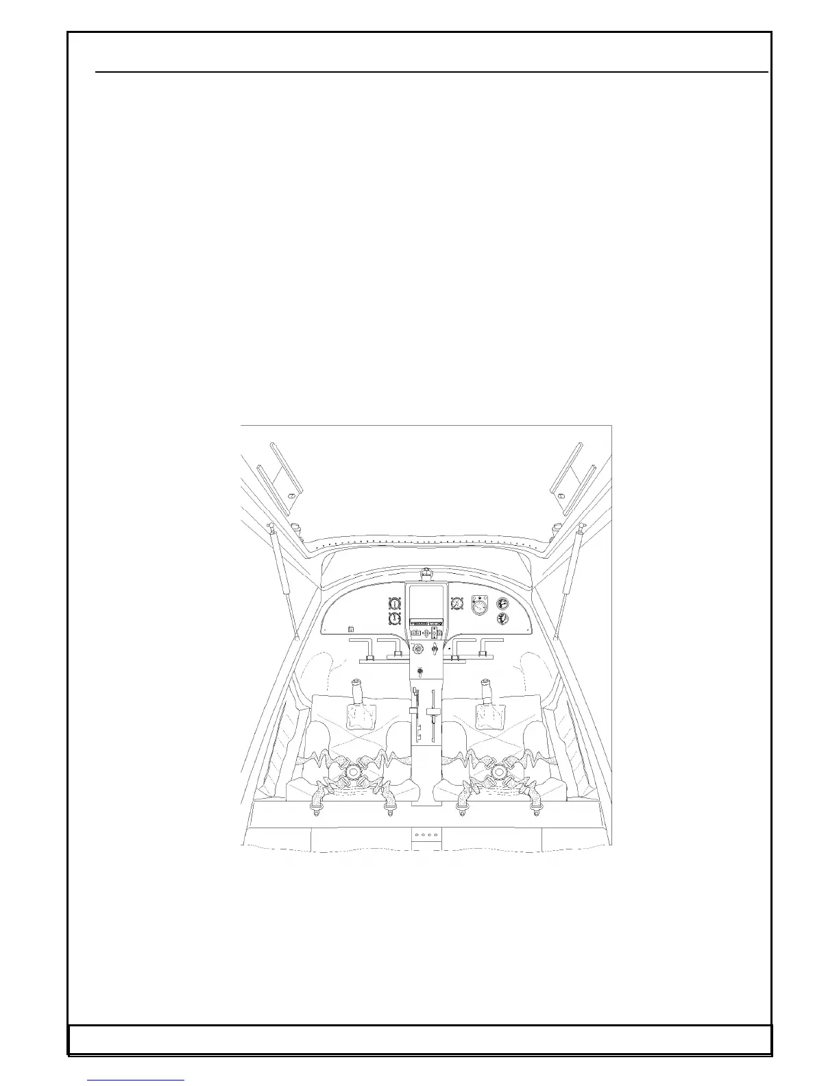
The standard cockpit arrangement is shown in the following figure. Instrument panel
arrangement is described in par. 1.6.8.3.
Fig.7. Cockpit arrangement
1. Control stick 9. Instrument panel
2. Rudder pedals 10. Ventilation sliding window
3. Elevator trim control lever 11. Ventilation flow baffle
4. Brake control lever 12. Fuel tank selector
5. Wing flaps control lever 13. Chock and throttle lever
6. Pocket 14. Ignition, Starter key, Master
7. Headset socket / jack 15. GPS, Radio, Transponder
8. Seat and safety belt 16. Powerplant instruments
17. Flight instruments
Date: