FILE VER LAST ISSUE LANG. PAGE
GCM02-MT-ING4 NEW.doc c/02 04/03/2003 ENG Page 16 of 57
2.D. Following the STARTING DELAY phase 4 starting cycles of 5 seconds each start, split up by pauses of 5 seconds (these may
be programmed).
2.E. At the end of the start cycles if the gen-set has not started, there is the FAILED START signalling, if the gen-set starts but it
doesn’t reach the speed values, after 120” there will be the min voltage or frequency alarm.
2.F. With the motor running at a steady state the voltage output by the generator is read. When this is within the established
parameters the generator delay timer is triggered (this may be adjusted from 1 sec. to 30 min. approx.). At the end of this
timing the generator (CG) contact maker is closed on.
2.G. By means of a normal VDO probe for reading the motor temperature the minimum temperature beyond which the load output
is enabled can be programmed. This is to prevent operating at a low temperature in the case of the failure or failed pre-heating
of the motor.
2.H. While the generator is running two pre-alarm safety devices are enabled, oil pressure and motor temperature. When these trip
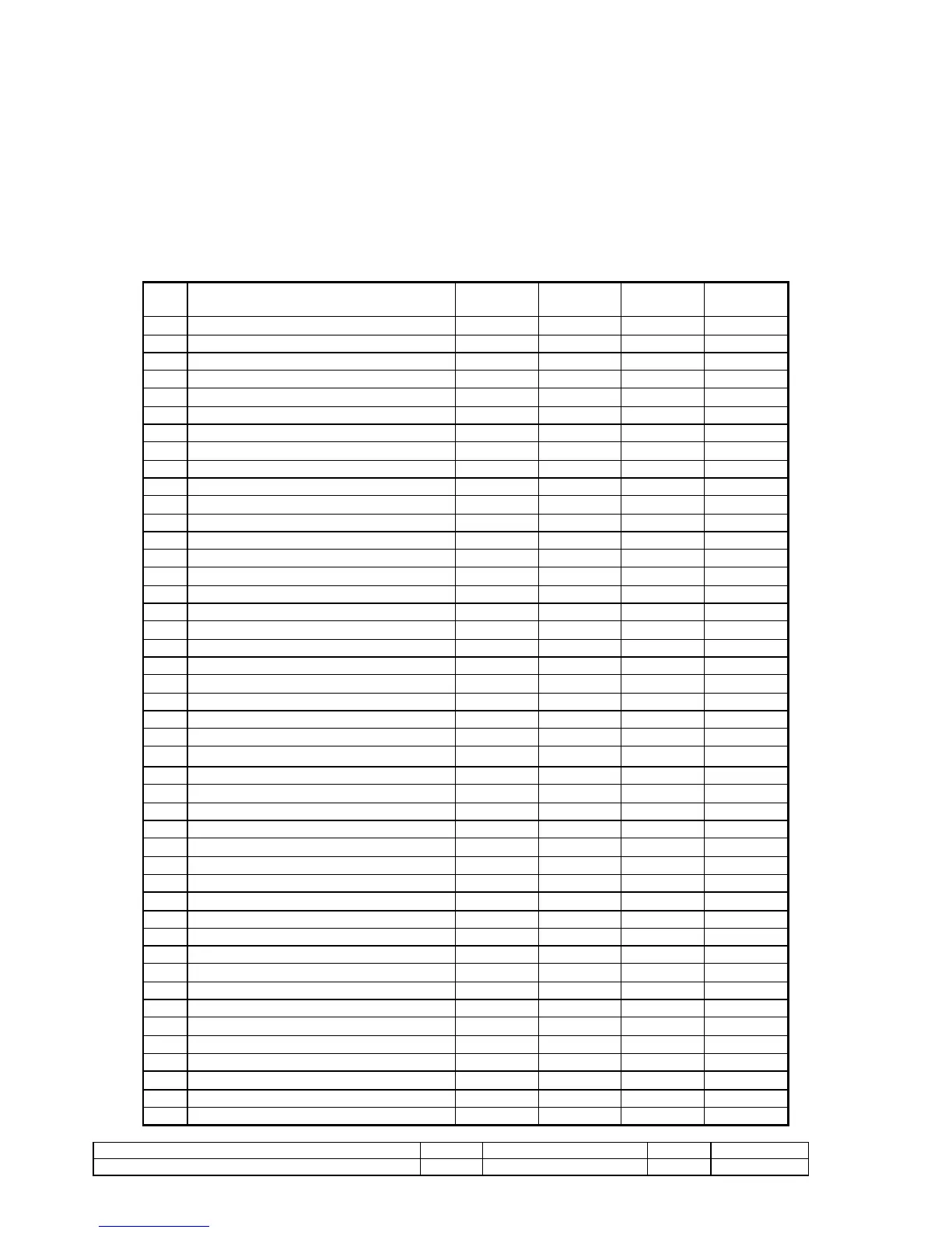
a buzzer sounds. The following safety devices and indications, when tripped, are displayed and trigger the programmable
functions described:
No. DESCRIPTION ON DISPLAY LED COLOUR
DELAYED
STOP
MOTOR
1 Failed starting A
2 Failed stoppage A
3 Low oil level A
4 Low oil pressure A YES
5 Minimum oil pressure (pre-alarm) A
6 High oil temperature A SR
7 Low water level A
8 Very high water temperature A YES
9 High water temperature (pre-alarm)
10 Battery charger generator A YES
11 Lack fuel A
12 Low fuel level (pre-alarm) A
13 Starting R
14 Stoppage R
15 Fuel pump running (ON) V
16 Minimum temperature A
BATTERY
17 Battery connected V
18 Excessive battery voltage A
19 Low battery voltage A
20 Battery charging V
21
GENERATOR
22 Excessive voltage (59) A YES
23 Low voltage (27) A SR
24 Overload (51) A SR
25 Short-circuit (50) A SR
26 Maximum frequency (81) A YES
27 Minimum frequency (81) A SR
28 Phase sequence A
29 Inverted power A SR
30 Generator connected G
30 Generator contact maker closed (ON) G
32 Differential trip switch (earthing fault) A SR
33
MAINS
34 Mains connected V
35 Excessive voltage (59) V OFF
36 Low voltage (27) displacement V OFF
37 Overload (51) A SR
38 Phase sequence A
39 Mains contact maker closed G
VARIOUS
40 Emergency push button pressed A YES