FILE VER LAST ISSUE LANG. PAGE
GCM02-MT-ING4 NEW.doc c/02 04/03/2003 ENG Page 55 of 57
WARNING considering that the battery charger generators output a voltage of between 50 and 150 Volts when
disconnected from the battery while the generator is running, which is very destructive for the electronics, the
connections must strictly not be touched while the generator is running or the loose cables.
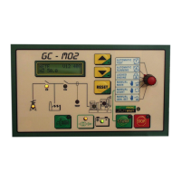
2.19.4. GC-M02 BOARD REPLACEMENT PROCEDURE
Ø Disconnect the BATTERY CHARGER and BATTERY fuses
Ø Set the programming switch on LOCK mode and replace the board.
Ø Copy the programming of the SW1 and of the JUMPERS situated on the replaced M02.
Ø Re-connect fuse F1 to the battery.
Ø Program the operational voltage and the frequency if different to the standard 400V 50Hz.
• Ration of the TA ...../5°
• Overload current, enter the rated current that may be output by the generator plus 5%.
• Short-circuit current, enter the overload current multiplied by 3.
• Compare the remaining values with the test board.
Ø The settings of the type of test TA, the overload and short-circuit current are crucial.
Ø Re-connect all fuses and check the efficiency.
WARNING the wiring to the terminal contactors may introduce residual voltages into the M02, which may generate a value for a current
that does not exist. To eliminate this go into the measurements menu, zero the current and press Reset. The M02 starts self-programming. This
operation must be carried out without current in the power circuits. Where this charge cannot be eliminated, short circuit the wires to the Terminal
Contactors.
2.19.5 MP02 POWER BOARD REPLACEMENT PROCEDURE
WARNING! It is absolutely prohibited to touch any parts while they are powered.
Ø Disconnect the mains and stop the generator if this is running.
Ø Disconnect the BATTERY CHARGER and BATTERY fuses
Ø Replace the board paying utmost attention to terminals 3 and 4 of the 12 and 24V voltage.
Ø If the motor is pre-arranged for positive inputs, program the relative JUMPERS and SWITCHES under the guard of the MP02 board, see
the “positive motor protection inputs” and “motor parameter analogue reading inputs” sections.
Ø Re-connect the battery and battery charger fuses.
Ø Check the efficiency of the unit.
WARNING the wiring to the terminal contactors may introduce residual voltages into the M02, which may generate a value for a current
that does not exist. To eliminate this go into the measurements menu, zero the current and press Reset. The M02 starts self-programming. This
operation must be carried out without current in the power circuits. Where this charge cannot be eliminated, short circuit the wires to the Terminal
Contactors.