FILE VER LAST ISSUE LANG. PAGE
GCM02-MT-ING4 NEW.doc c/02 04/03/2003 ENG Page 19 of 57
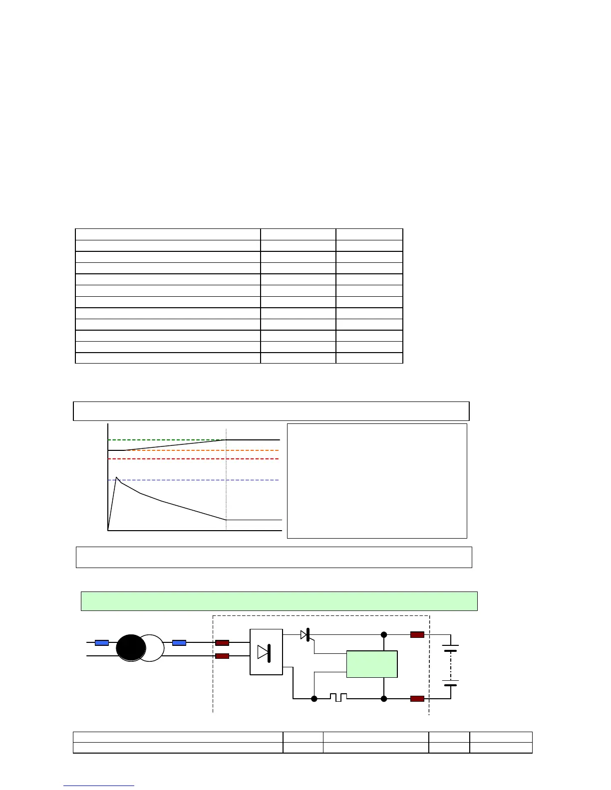
2.5.5 AUTOMATIC BATTERY CHARGER
The automatic battery charger is the double semi-wave type with phase choker, totally controlled by the micro-controller. It keeps the
starting battery charged with a max. load of 8A and the charge is self-adjusted to compensate for consumption and for when the battery
automatically runs flat. The voltage of the battery and the charging current can be displayed on the GCM02 unit.
The electronics are built in the MP02 unit whereas the battery charger transformer is fitted externally.
It is equipped with:
• Automatic cut-out of the charge during the starting phase;
• Electronic restriction of the current to prevent excessive loads;
• Electronic restriction of the voltage to limit the maximum load levels (2,3 V/E) 13,5/27V.
• Protection against short-circuits.
• Protection against inverted polarity.
• Protection against excessive input voltage.
• Auto programming of the voltmeter thresholds on the battery voltage
• Protection with low battery voltage for excessive discharge
• Programmable values also for batteries Nichel Cadmio.
Technical features
Programmed work voltages 12 V 24 V
Work frequency 50 and 60 Hz 50 and 60 Hz
Max programmable current From 1 to 8 A From 1 to 8 A
Max voltage threshold 14,5 V 29V
Alarm voltage threshold 10,8 V 21,6 V
Battery charter transformer Min Max
Voltage II° for battery 12V 17 Vac 20 Vac
Power in VA/A for battery 12V 50VA / 3 A 150VA / 8 A
Voltage II° for battery 24V 29 Vac 32 Vac
Power in VA/A r batt. 24V 100VA / 3 A 250VA / 8 A
PROGRAMMING
To set the value of max current of charge on the power of the installed transformer