FILE VER LAST ISSUE LANG. PAGE
GCM02-MT-ING4 NEW.doc c/02 04/03/2003 ENG Page 17 of 57
41 CR mains contact maker anomaly G A
42 CG generator contact maker anomaly G A
2.I When an alarm is triggered and the generator is stopped, the following occurs:
• The alarm triggered appears on the display.
• The generator contact maker is immediately opened.
• Activation of the immediate stop SI or delayed SR after the phase of cooling motor (if enabled stop)
• Activation of the acoustic alarm and lighting of the flashing red led on the drawing of the engine.
• The alarm cause is saved.
• The LOCKED status is triggered until the alarm is reset, the first impulse to SILENT /RESET/ACK button it silents the acoustic
alarm, it recognizes the alarm with function ACK (function ISA M) and the alarm led from flashing it becomes fixed, to restore the
functions excluding the block for alarm, to press a second time the RESET button and alarm red led will be turned off.
2.J. When the voltage returns within the rated parameters the switch back to mains delay timer is triggered that enabled the mains to
settle before switching back the load.
2.K. Once the load is switched, the motor cooling phase of roughly 1 minute begins. At the end of this phase the immediate or delayed
stoppage phase is enabled.
2.L. Pre-arrangement for a new cycle
2.M. With the mains connected the overload safety device (51) of the mains contact maker is enabled (EXCLUSIVE) , which when
tripped, triggers the buzzer without interfering with the mains output, warning the operator that the rated current of the CR contact
maker has been exceeded.
2.N. To the command of the contactors CR and CG it is done the control of the real closing, contrarily there is the alarm (it is activated
inserting the ADJUSTABLE DELAY).
2.O. If there is a stop not trained (DELAY STOP TO ZERO) the Ge supplies with any alarm, the gen-set can be stopped only manually
2.P. The change of the switching from CG to CR or from CR to CG, it is alternated by a break of 1”, to avoid a malfunction of the
mechanical interlock
3 LOCKED STATUS
3.A. It immediately stops the generator if this is running.
3.B. It disconnects the power supply from all starting circuits.
3.C. it ensures safety throughout maintenance.
It deactivates the fuel pump and the preheating in order to there is not any components in voltage during the maintenance.
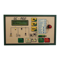
2.4 MANUALLY CONTROLLED FUNCTIONS
The manual operational mode is considered as an emergency back-up mode for the automatic functions. It also ensures the operating
efficiency with the micro-controller in an abnormal condition. The programming switch ensures the direct commands that are not
backed-up by electronic logics. This means that when the START push button is pressed for example, the starting motor will be
operated for as long as the push button is held down.
The following functions are possible:
1. Forced power supply from the mains CR;
2. Manual starting, the generator CG contact maker is opened;
3. The mains CR contact maker is opened and the power supply is forced from the generator;
4. Manual stoppage;
2.4.1 POWER SUPPLY FROM MAINS (manual command)
This enables the mains power supply permanently and disables all the electronic functions with the exception of the battery charger and
the EMERGENCY stop function.
2.4.2 MANUAL STARTING
Enable the start button, and the 15/54 relay that provides power to all the unit’s services (solenoid valves, actuator, etc.) will be activated
simultaneously.
2.4.3 POWER SUPPLY FROM GENERATOR
Once the unit is running in normal mode, switching the commutator to GENERATOR POWER SUPPLY causes the contactor for the
Generator unit to close, and the unit then draws power from the generator.
While the unit is supplying power all the trip switches are active. However, since these are entirely controlled electronically, any fault in
this system could render it inactive.
2.4.4 MANUAL STOPPAGE
The stop push button is enabled at all times. Press it until the motor stops completely.
By moving the jumper 1 on the MO2 module the stop push button is enabled only when the programming switch is in MANUAL START
mode.